
 | ||
| Metropower Portal | ||
| ||
 Midas Cortez kit car Midas Cortez kit carModerators: Jump to page : 1 2 Now viewing page 1 [25 messages per page] | |
| Gallery-> Non Metro gallery | Message format |
| Jin |
| ||
| Regular Posts: 159    | Hi all Thought it time I shared what ive been getting up to over the last 12 months and rather than me just ask questions all the time i thought id share what its all been about this car has already appeared on here prior to my ownership, http://www.metropower.org.uk/forum/forums/thread-view.asp?tid=19729&start=1 it was the factory prototype built in 1995 I originally announced ownership here http://www.metropower.org.uk/forum/forums/thread-view.asp?tid=81087&posts=4 at that time (AUG 2014) The list of jobs included Re-trim (but for now I’ll settle for ripping the carpet out and burning it) Stop all the rattles Sort bonnet alignment Sort doors alignment Sort boot alignment Sort glass alignment Sort bodywork And that’s just for a start. Planned modifications include New back lights (on order) DAB radio (on order) New steering wheel because i can’t reach the current one (on order) Coil over conversion New alloys (if i can ever find any to fit??) De-cat Lastly a couple of pics In its new home 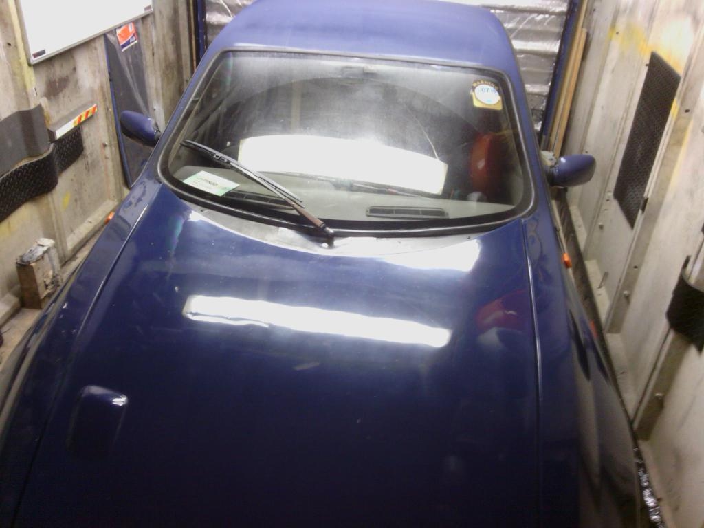 The stickers  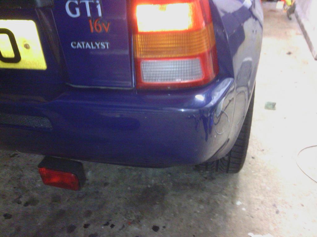 gone thank god Bonnet alignment before 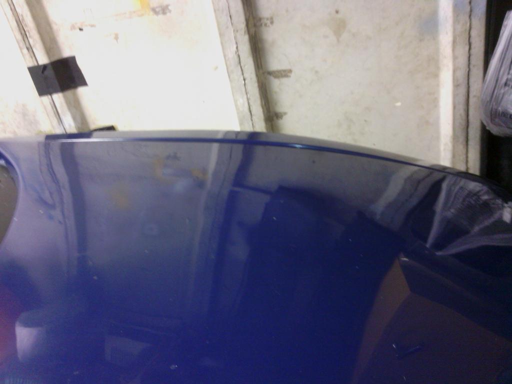 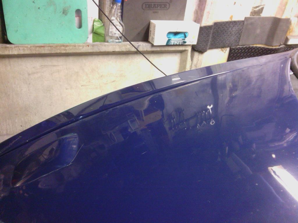 After adjusting the centre catch and making rubber chocks to sit in the middle 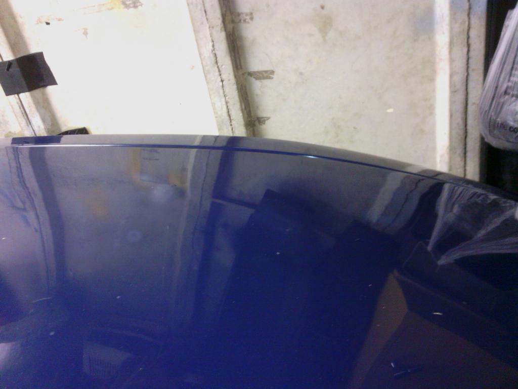 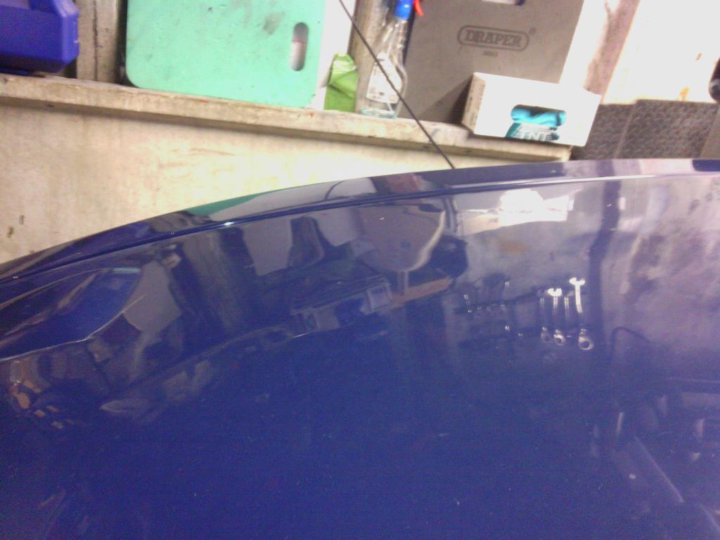 Not perfect but a work in progress SEPT 2015 The bonnet realigning moved into its last phase (can’t believe how long its took) which focused on the rear edge, For a start the bonnet was jacked up on 2 cut down rubber mount bobbins to make crude bumpers, these were part to blame for the ½” gap round the rear edge. With those removed and the latch pulled down as far as it would go the fit was better but nowhere near right All that was left to do was tweak the catch pin mounted on the bonnet, with that removed and a base measurement took And then re-bent to suit Refitting saw it not latch properly due to being pushed further out, so remounting it on the bonnet 10mm further down did the trick, now with the latch adjusted to suit the rear gam is almost mm perfect, a few cycles of hot / cold hot /cold from the engine should see it follow the curve of the wing tops more readily The end result looks pretty good I think [url href="http://s120.photobucket.com/user/jindal/media/jindal016/IMG_20140905_073708_zpsj5nopfbm.jpg.html"][img src="http://i120.photobucket.com/albums/o192/jindal/jindal016/IMG_20140905_073708_zpsj5nopfbm.jpg"] [url href="http://s120.photobucket.com/user/jindal/media/jindal016/IMG_20140905_124937_zpspzutj3xm.jpg.html"][img src="http://i120.photobucket.com/albums/o192/jindal/jindal016/IMG_20140905_124937_zpspzutj3xm.jpg"] Compared to how it used to look [url href="http://s120.photobucket.com/user/jindal/media/jindal016/IMG_20140813_161520_zpsoyul66ad.jpg.html"][img src="http://i120.photobucket.com/albums/o192/jindal/jindal016/IMG_20140813_161520_zpsoyul66ad.jpg"] Since I had to remove the scuttle panel to get better access to the catch and since it looked proper ropey I thought it a good idea to make a new one while I was at it [url href="http://s120.photobucket.com/user/jindal/media/jindal016/IMG_20140905_125315_zpsamsilan5.jpg.html"][img src="http://i120.photobucket.com/albums/o192/jindal/jindal016/IMG_20140905_125315_zpsamsilan5.jpg"] [url href="http://s120.photobucket.com/user/jindal/media/jindal016/IMG_20140905_151217_zpserjkfbvf.jpg.html"][img src="http://i120.photobucket.com/albums/o192/jindal/jindal016/IMG_20140905_151217_zpserjkfbvf.jpg"] The old one was cracked and had shabby looking self-tappers holding it into place, so I bought some textured plastic core board since its very strong and lightweight, cut it slightly oversize to fill the gaps a bt better and divert rain further away from the bulkhead, [url href="http://s120.photobucket.com/user/jindal/media/jindal016/IMG_20140910_223627_zpslkqwl7cm.jpg.html"][img src="http://i120.photobucket.com/albums/o192/jindal/jindal016/IMG_20140910_223627_zpslkqwl7cm.jpg"] [url href="http://s120.photobucket.com/user/jindal/media/jindal016/IMG_20140910_223919_zpsvnig4sqw.jpg.html"][img src="http://i120.photobucket.com/albums/o192/jindal/jindal016/IMG_20140910_223919_zpsvnig4sqw.jpg"] Made a new ally bracket to mount it and held in place with a single hidden self-tapper (bonnet closed) Then for neatness I’ve just fitted a single washer jet tucked into the V of the bonnet, all in I’m happy with the outcome and will now focus on the doors More progress The annoying clacking noise emanating from the front bulkhead / dashboard area has been pin pointed to the steering column bottom bearing being goosed, so a replacement was demanded off a metro breaker off ebay along with the wiper stalk too since that didn’t work either Im always dubious about buying second hand car parts off ebay (and with good reason too, when I built the quantum and needed the driver’s side XR2 tie rod bracket I had to have 3 attempts to get the part in a useable condition, the first was so bent from a front end shunt the 3 bolt holes ended up a 45 degrees to each other and the second looked like it had been gnawed off by an angry badger) but in this instance the part was in such good condition it could have easily passed for new both visually and physically so I’m very happy and it was put to good use. 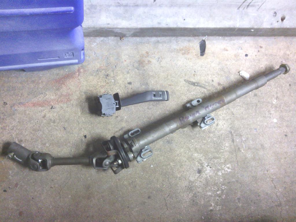 All fitted in and no clackety clackety clack 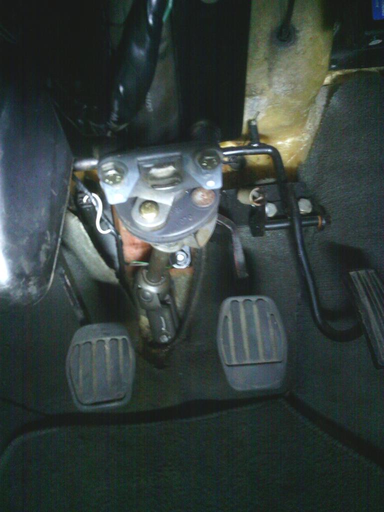 Next the cat, the heat shield welded under it has rotted and rattles like mad, then the cat itself hits the upper heat shields on the move again making annoying noises, the decision was taken to fit a de-cat pipe in place, since this is pre K reg I’ll probably get away with it as back then the standards were pretty low (not like removing it from a 2014 car anyway) so we shall see, I’ll hang onto it just in case, after drenching the nuts in WD40 for 3 days it made all of no difference, when you’ve got yer best spanner on the nut and 1 foot tuber for leverage and your pulling so hard your dragging yourself across the garage floor and its still not shifting the nut you know you’re in trouble (not as much trouble as I could have been had I not had good reason for the subsequent scratches down my back when the wife asked, note to self, must carpet garage) and I didn’t fancy heating it up either with it being so close to the body. After a bit of head scratching I chocked the exhaust to the body with wood so it couldn’t move, then put spanner on nut with a trolley jack under the spanner, the car literally lifted 3” or so before any movement on the thread at all, I don’t think ive ever had nuts that tight before (sblack person) With the old cat out the way it was just time to realise the de-cat pipe was made by someone working from a blurry photo, so my new shiny pipe had to be tweaked with a large hammer and a bench vice, I didn’t feel happy with what I had just done but it fitted and only hit the heat shields most of the time, Lowering the rear exhaust hanger did the trick of providing more clearance in the end and nothing looks too bad after all. Old cat 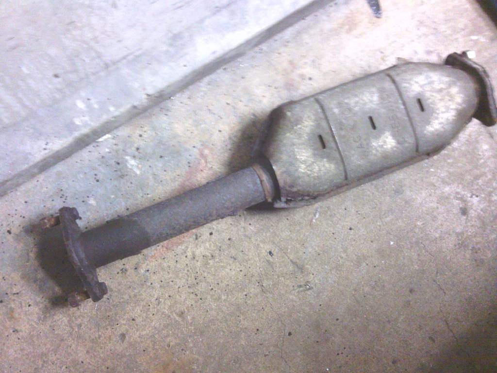 No cat 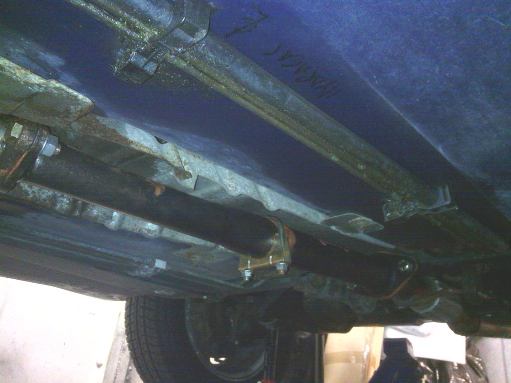 My cat  The drive to work this morning was the quietest yet with only 3 annoying rattles (one may have been down to me leaving the boot open) so it’s actually becoming quite refined, The down sides of this work is spending so long under the car I’ve now noticed nearly all of the fuel and brake pipe clips are doing nothing to hold the pipes in place, that job is being taken care of by the anti-roll bars and cable ties (?) The windscreen wiper was letting the new scuttle panel down, It didn’t clear the glass in a full sweep and it parked itself right in my field of view First job was to look at the sweep, great thing with his car is once the dash top has fallen off the access to the wiper motor is perfect, a quick look saw a potential route to increase the sweep by straightening out the stepped crank attached to the motor spindle, this would also put it at a better angle in relation to the crank arm 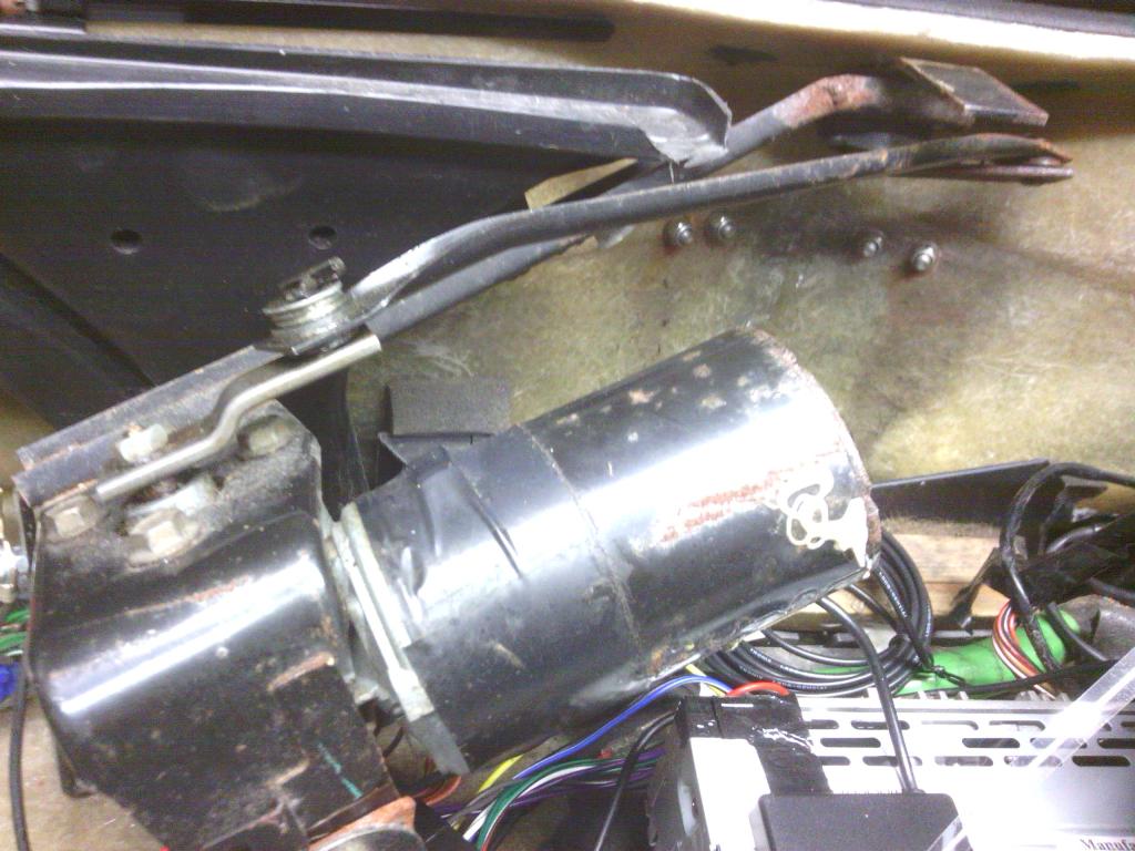 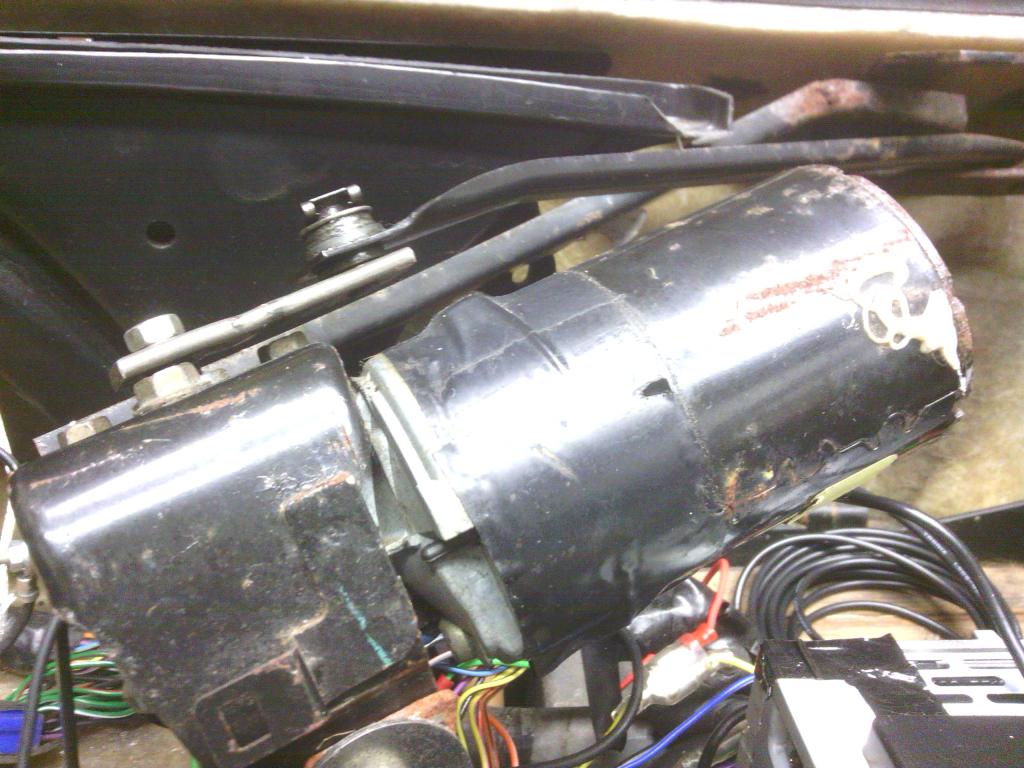 With that done the sweep has increased to a better level, you can see the difference where I put a bit of tape where the old setup stopped 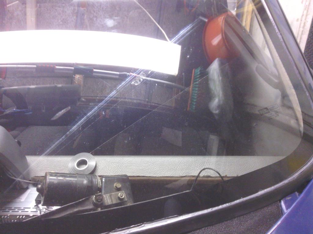 Next the motor crank was turned 180 degrees to park the blade over the passenger side 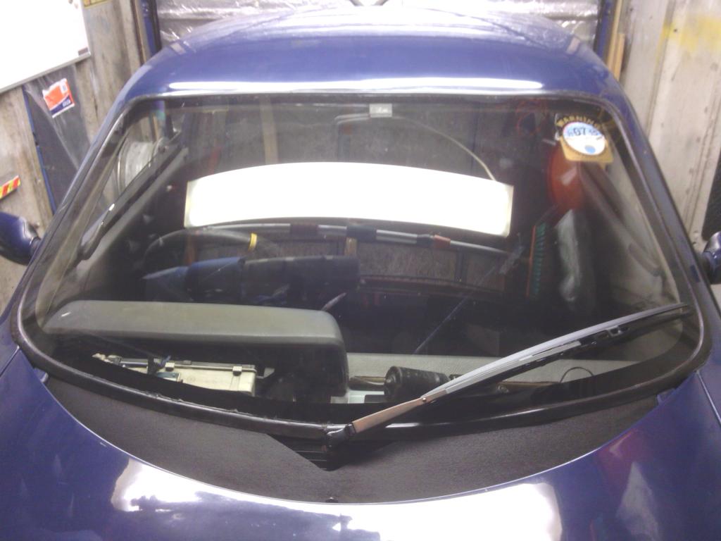 Better Now the arm itself looked proper tatty. Quick mooch on ebay saw a Citroen Picasso rear wiper to be the same length / fitting and perfectly straight, and its stylishly moulded in plastic so it wont go rusty again 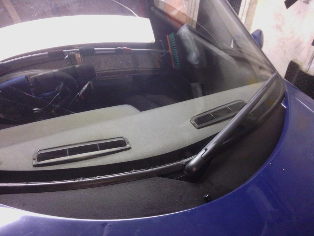 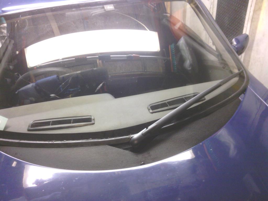 Both doors (but the drivers was worse) had dropped on the hinges causing them to look out of line a fair bit, plus I need to sort the glass height soon so it would be wise to get the doors true first as a good datum, Thankfully there is no play in the hinges so it was just a case of (I thought) elongating the holes either top or bottom or both and tightening the nuts I was a bit apprehensive since the washers behind the nuts look a bit shoddy (well down right terrible if I'm honest, I can't stand cut down washers), but either way I set to work safe in the knowledge I've plenty more while washers [url href="http://s120.photobucket.com/user/jindal/media/jindal016/IMG_20140918_221643_zpsluxur8vm.jpg.html"][img src="http://i120.photobucket.com/albums/o192/jindal/jindal016/IMG_20140918_221643_zpsluxur8vm.jpg"] Once I removed the washers it soon became apparent I needed a plan B. I certainly didn't need my round file to "neatly slot the holes" as I thought since it looked like they were originally made using a shotgun. [url href="http://s120.photobucket.com/user/jindal/media/jindal016/IMG_20140919_232239_zpssdngreut.jpg.html"][img src="http://i120.photobucket.com/albums/o192/jindal/jindal016/IMG_20140919_232239_zpssdngreut.jpg"] So onto plan B I didn't fancy layering up more penny washers so I made some spreader plates out if 5x 50mm section extruded aluminium (cos it's tougher than rolled sheet) then grit blasted them to give a grip into the fiberglass to prevent slippage over time [url href="http://s120.photobucket.com/user/jindal/media/jindal016/IMG_20140918_221930_zpsgh4ufwwi.jpg.html"][img src="http://i120.photobucket.com/albums/o192/jindal/jindal016/IMG_20140918_221930_zpsgh4ufwwi.jpg"][/URL With the doors accurately chocked using laminate floor packers which come in handy making comparisons side to side [url href="http://s120.photobucket.com/user/jindal/media/jindal016/IMG_20140919_230201_zpsd1sfurcg.jpg.html"][img src="http://i120.photobucket.com/albums/o192/jindal/jindal016/IMG_20140919_230201_zpsd1sfurcg.jpg"] I fitted the plates with the holes filled up with polyurethane adhesive [url href="http://s120.photobucket.com/user/jindal/media/jindal016/IMG_20140919_234049_zpsiiv0yzxd.jpg.html"][img src="http://i120.photobucket.com/albums/o192/jindal/jindal016/IMG_20140919_234049_zpsiiv0yzxd.jpg"] Now the load is spread and the bolts are pulling evenly across the fiberglass, The doors a both adjusted to give a perfect gentle click upon closing and the shut lines are perfect, The upper hinges are nowhere as bad but they do have rusty washers so they will be treated to some nice thick stainless ones once mr postie man droppers them off Anythings got to be better than the old ones [url href="http://s120.photobucket.com/user/jindal/media/jindal016/IMG_20140919_234930_zpsiy1fajej.jpg.html"][img src="http://i120.photobucket.com/albums/o192/jindal/jindal016/IMG_20140919_234930_zpsiy1fajej.jpg"] So to begin with the lasts jobs, the seats – well the mounting of. I had noticed the seat sub frames had become – shall we say a tad rusty, 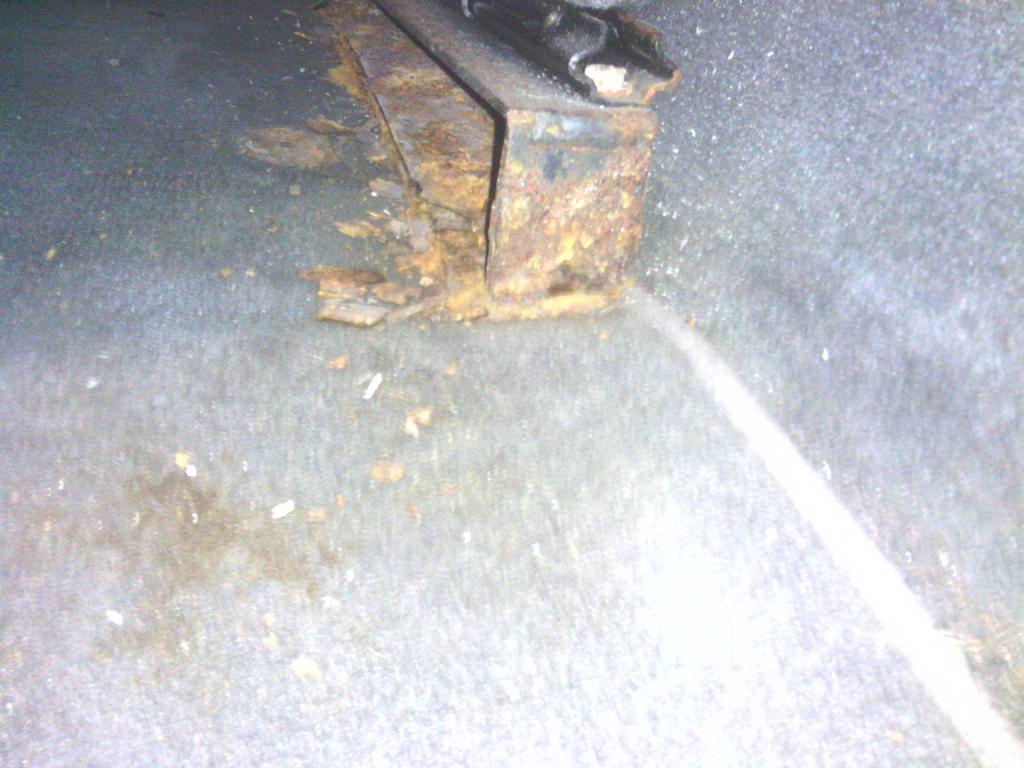 Further investigation showed the seat to not actually be attached to the floor in many places The fixing that pass through the floor didn’t look too clever either 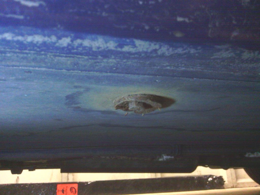 So I got out my trusty socket set and set about undoing the floor bolts, unfortunately all 4 were so corroded the heads were unidentifiable, there was no shape to grip onto, I couldn’t chisel them off either for risk of damaging the floor so my only option was to hold a hacksaw blade between my fingertips and slowly slice the heads off – about as much fun as finding worms in your ice cream The outer 2 were the worst probably due to being In the firing line from the wheel so I had hoped the inner 2 would at least surrender to the ,mole grips, thankfully one had the decency to shear in half 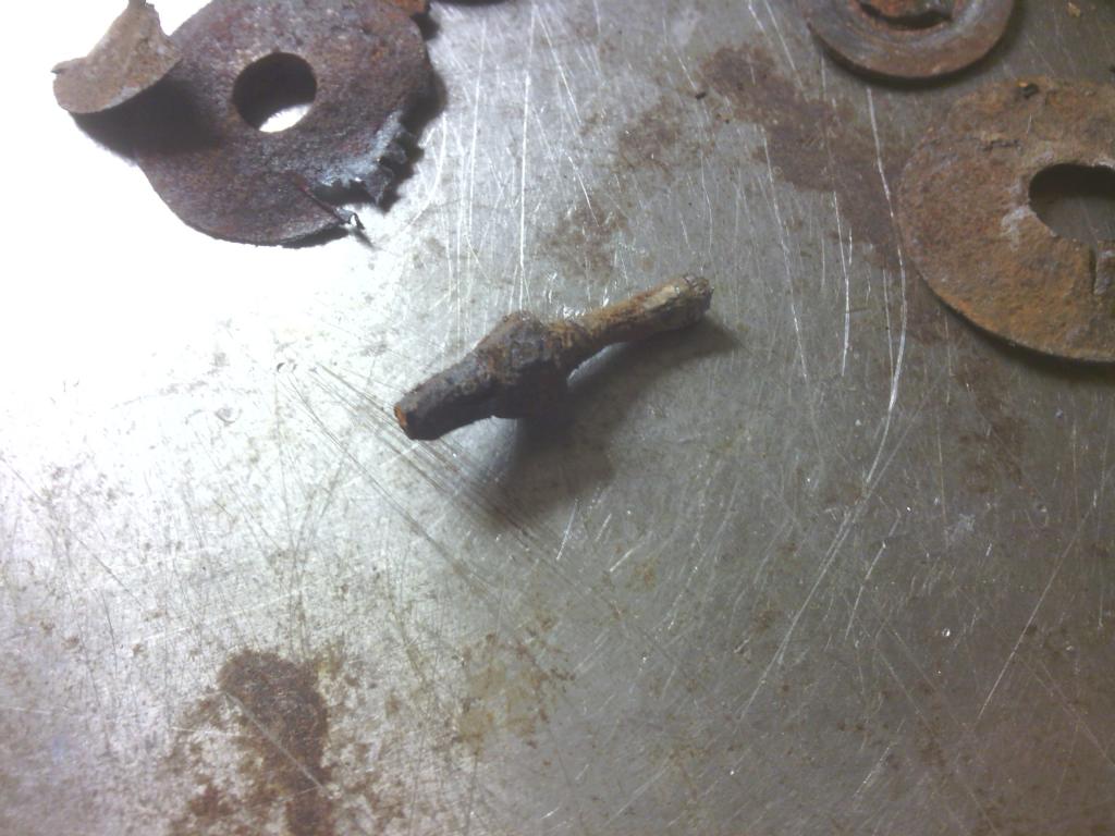 which just left one but by his point I was well and truly pissed off so I go the angry grinder out and lopped his head off as this bolt passed through the exhaust heat shield I felt it a safe bet. Seat out to fully appreciate the horrors 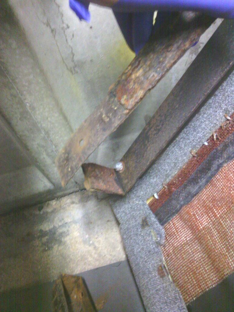 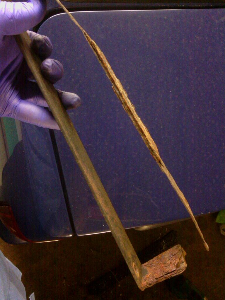 For a fiberglass car this is very rusty, even the carpet is rusty 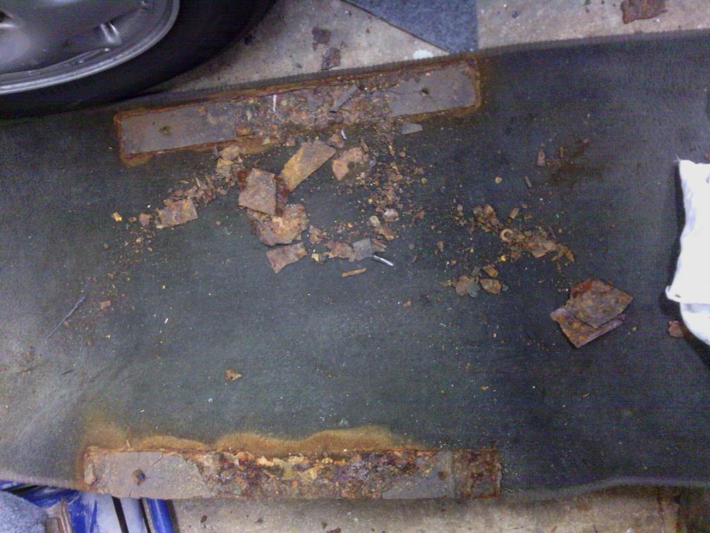 So new sub frames were needed, I didn’t like the original design since you’ve technically only got point contact front and rear, not much to spread the load down the floor, so I got hold of some galvanised cable conduit, its C section so easy to get to the fixings and 2.5mm thick so massively strong, 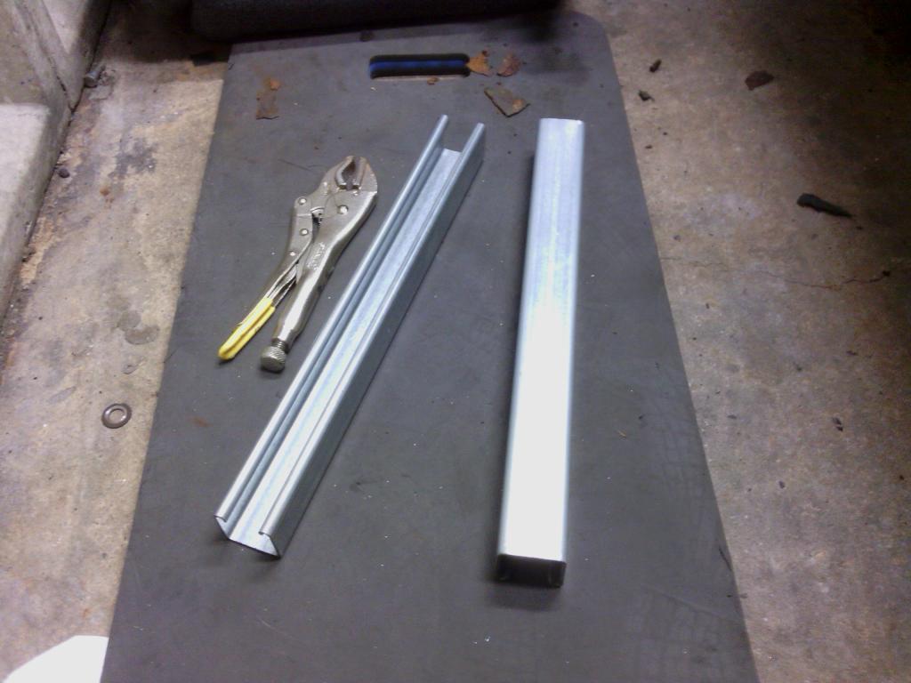 plan was to just bolt in place of the old sub frames and be happily on my way, but things never go to plan. The first attempt to do just that saw the floor show up to not be totally flat at the original fixings locations, 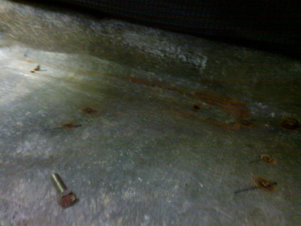 this is because the matting has been laid up to join the inner sills to the floor and the centre tunnel also intrudes into this area, not by much ad no problem for the flexible original sub frames but there is no give in the new ones so the runners just jammed solid So seat back out and a new flat location identified for the runners, approx. 40mm in from the originals 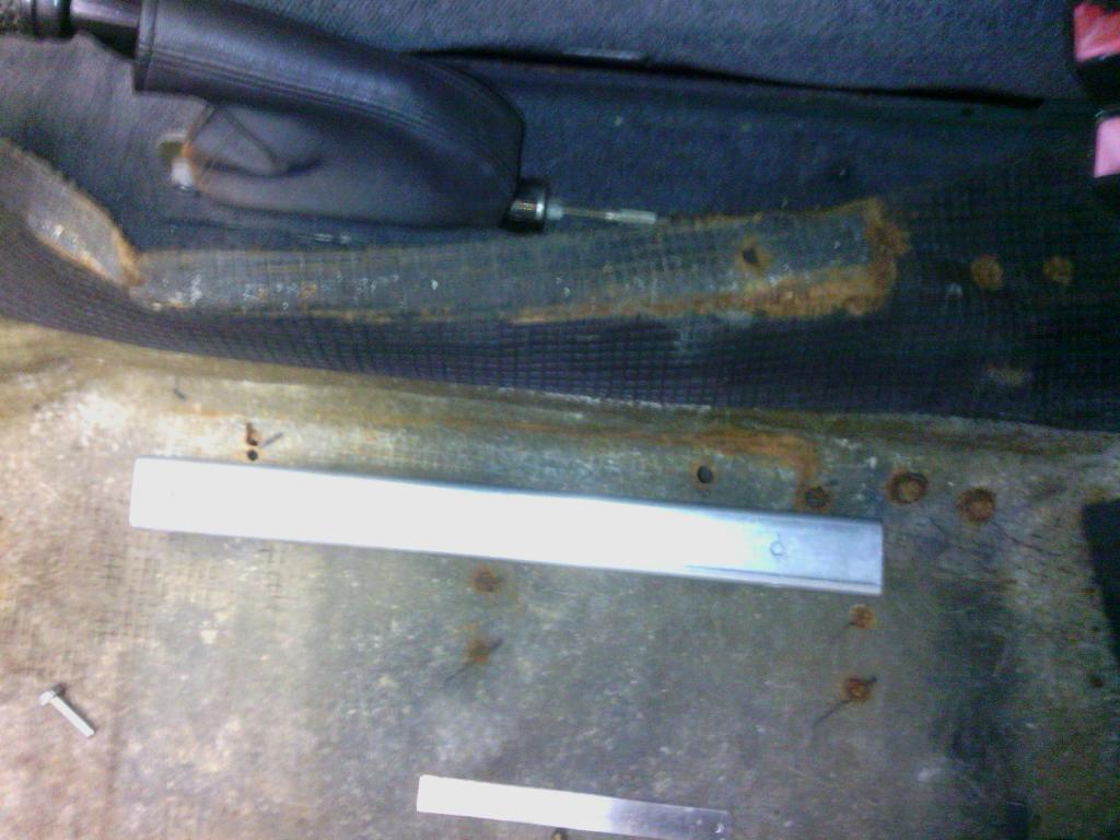 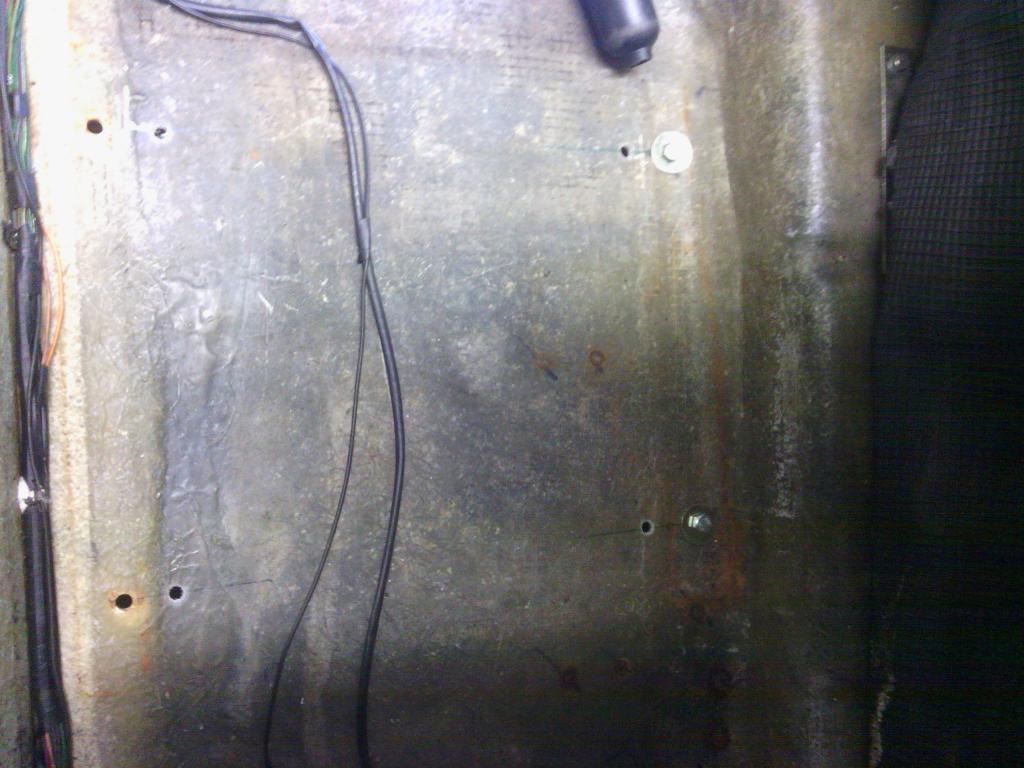 now the sub frames didn’t line up with the seat so I made some plates out of 6mm thick aluminium to allow the seat to fit to that, this is a good move since I don’t want to keep these seats for much longer and I now have a universal platform to mount the new seats onto 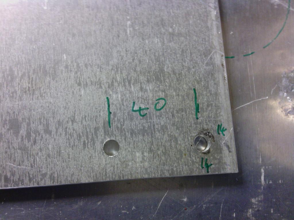 the end result 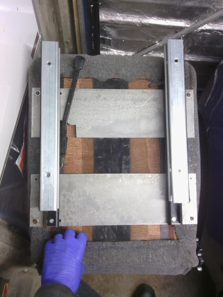 The original seat mount holes have been plugged up with M6 flange head stainless bolts and the new seat mounted down with M8 stainless flange bolts and nuts (M6 just doesn’t seem enough really) and the C section sub frames beaded down on a bead of polyurethane to prevent and moisture getting in between and to spread the load against and slight unevenness on the floor itself 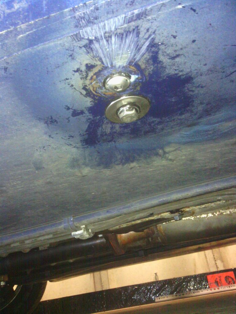 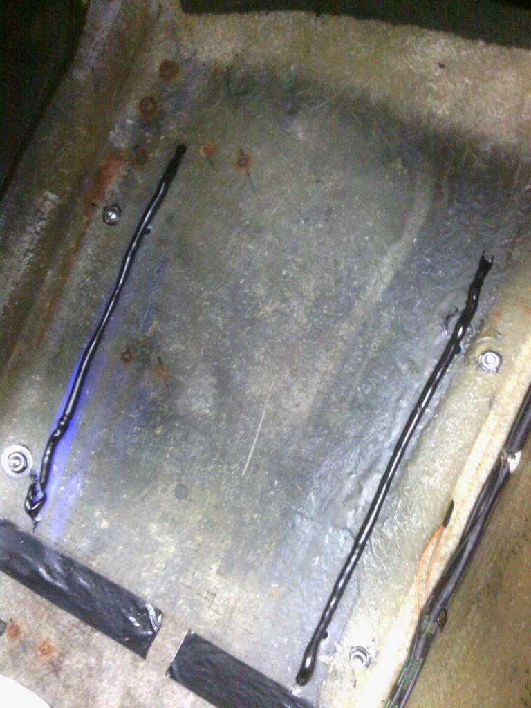 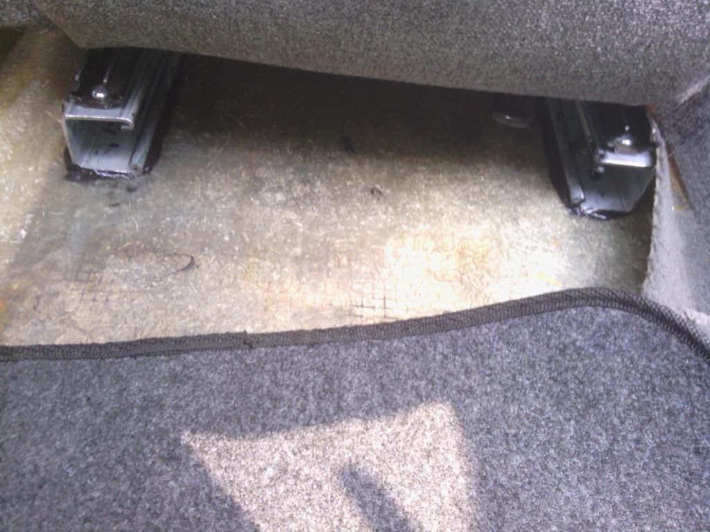 Then I had the pleasure of doing it all over again on the driver’s side, it’s all done now though and now I can drive the car safe in the knowledge my arse is safe with the added bonus I’ve been able to rip most of the carpet out now so the car smells slightly less like a tramps dog inside so a win win situation, for now I’m just rocking the no carpet race car look with a set of not very tailored mats from that well known car accessory emporium – ASDA. 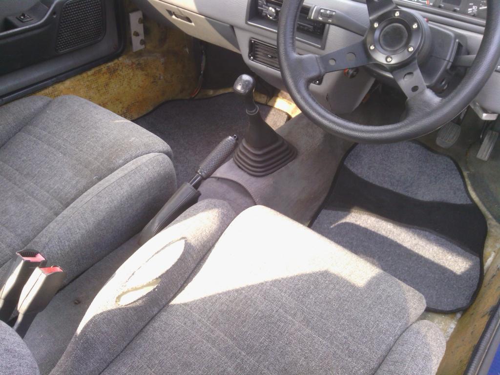 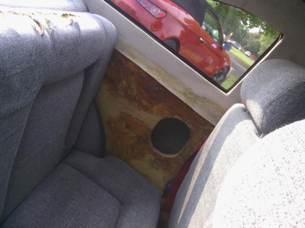 At least it will be easier to trace leaks. That’s all for now, that’s about a weeks’ worth of work there More to come soon I promise Stay tuned when I’ll be finding out how many attempts I can have to undo a seat belt bolt before I admit defeat and fiberglass over it and how many different methods of joining wires is it possible to cram into one 8” length?, is 4 enough or can we find more Edited by Jin 12/11/2015 2:17 PM | ||
| Jin |
| ||
| Regular Posts: 159    | Another job ticked off, I couldn’t stand the flippy flappy fog light under the rear bumper, the bracket was so rusty it spent most of its time pointing at the floor anyway 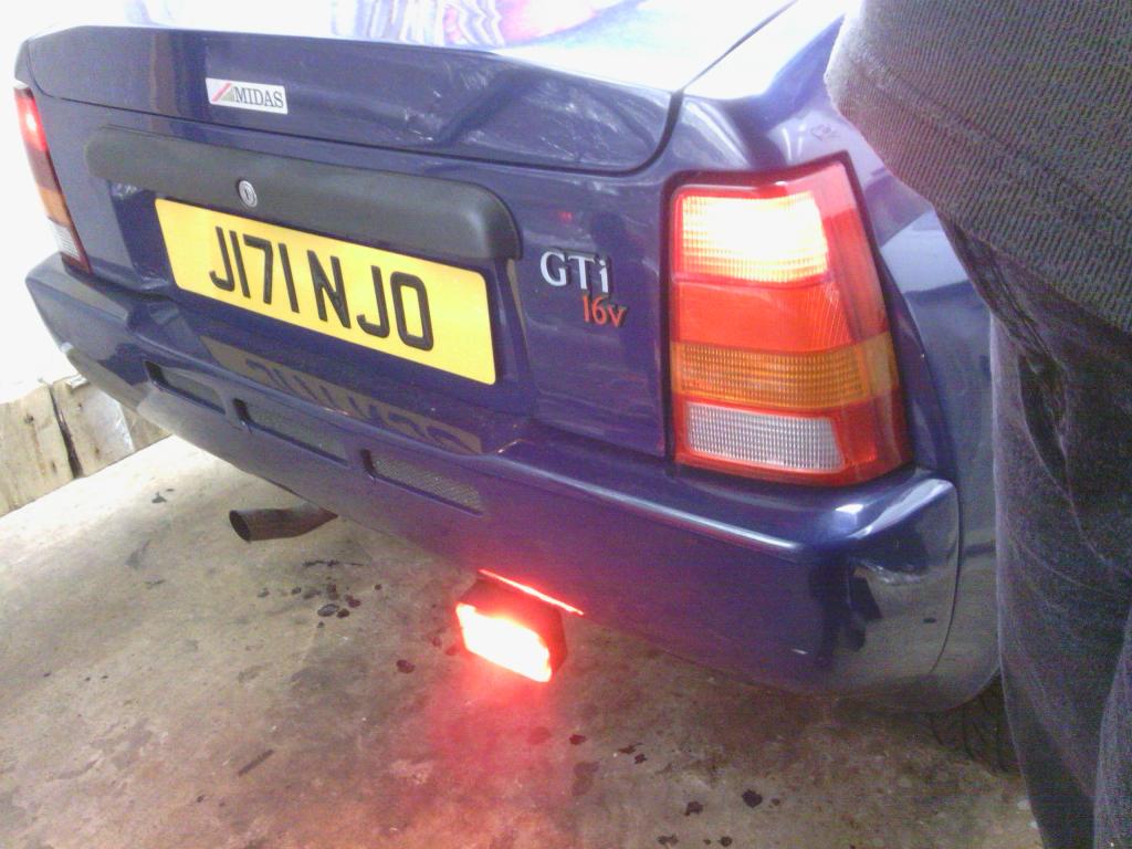 So I got myself a good quality (Philips) red bulb, fetched the old fog light off and stuffed the bulb into the right hand side reversing light housing, 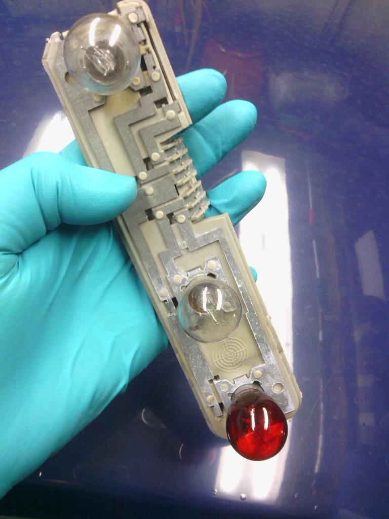 thought it would just be a case of re-routing the fog light wiring to the bulb holder but then I found the wiring “modification” on the tail light loom done to convert the metro loom to Astra tail lights, whoever was responsible had made a total monkeys breakfast of it so that had to be re-done first. 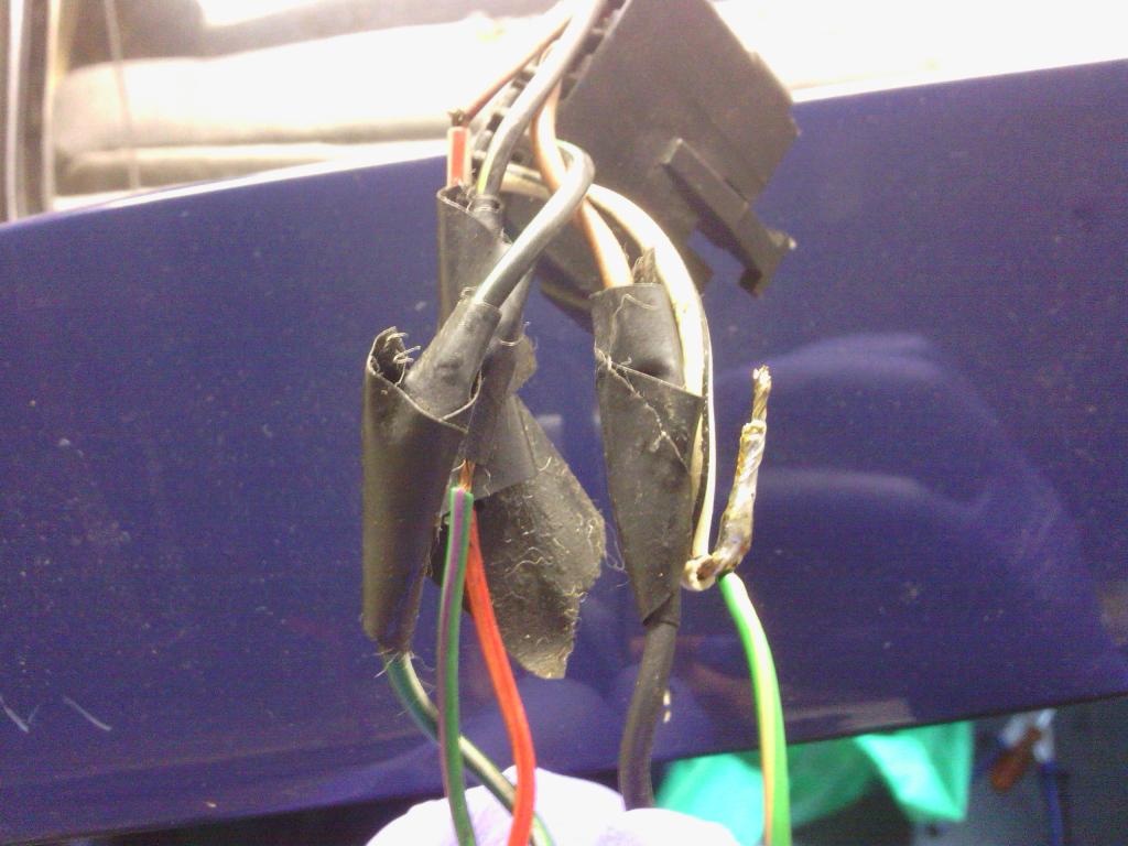 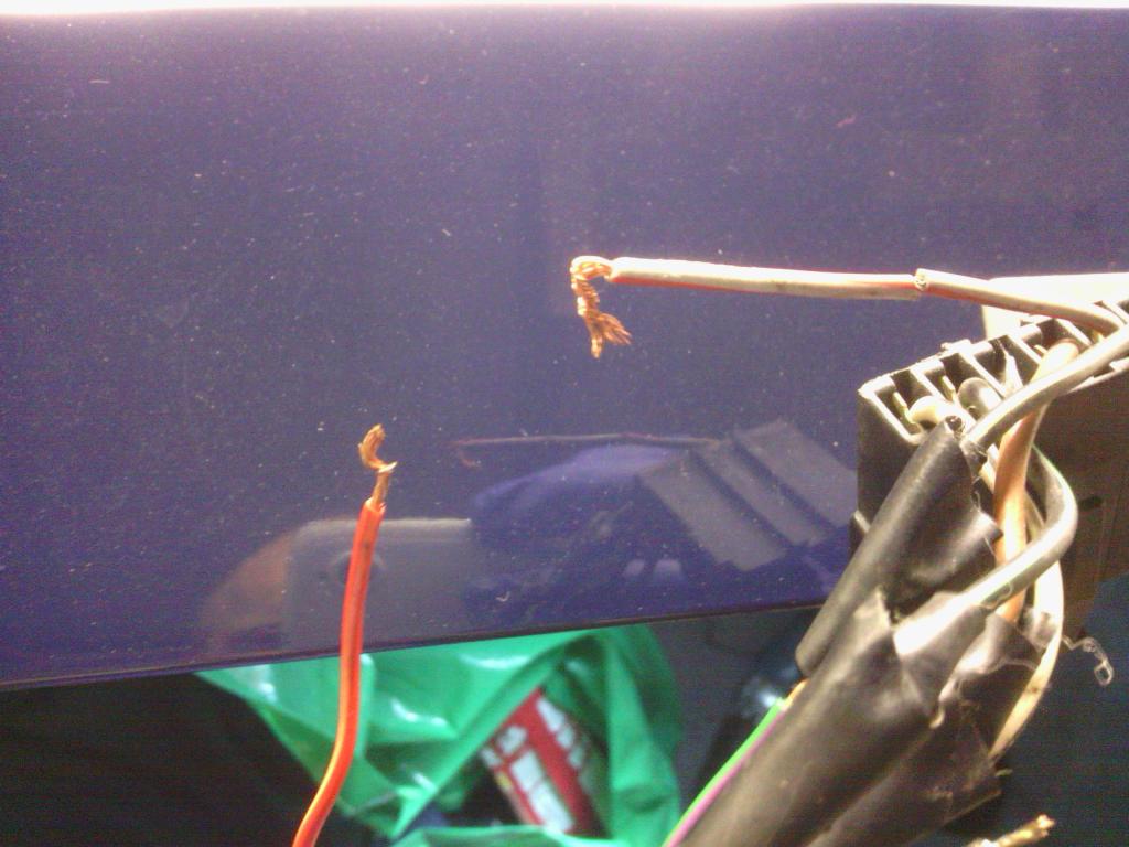 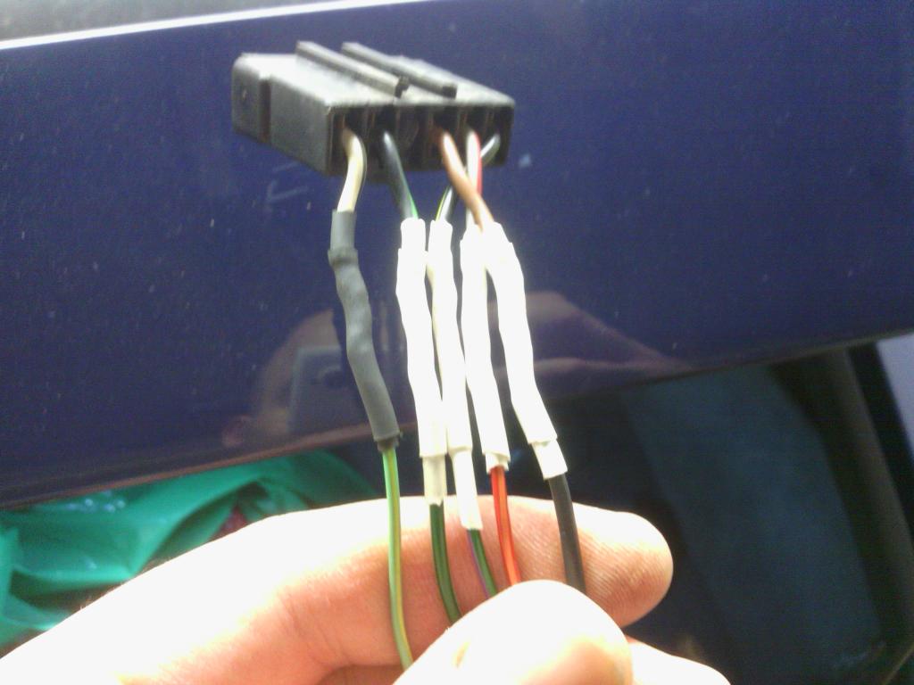 Then after a quick tidy up of some random wires just dangling around in the boot that I can find no use for I wired it all back in and jobs a good un. 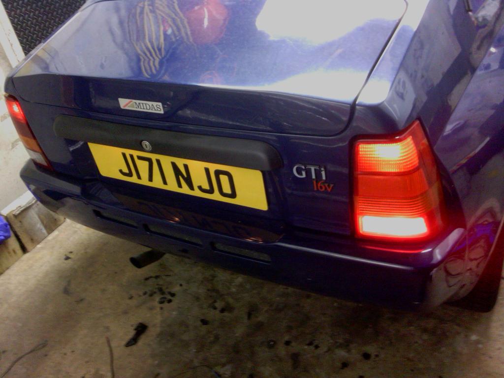 I did find these too 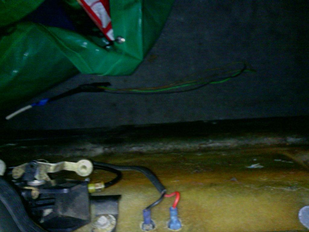 Can’t wait to find out what they’re supposed to do but on the whole for a quick job my rear end looks much nicer 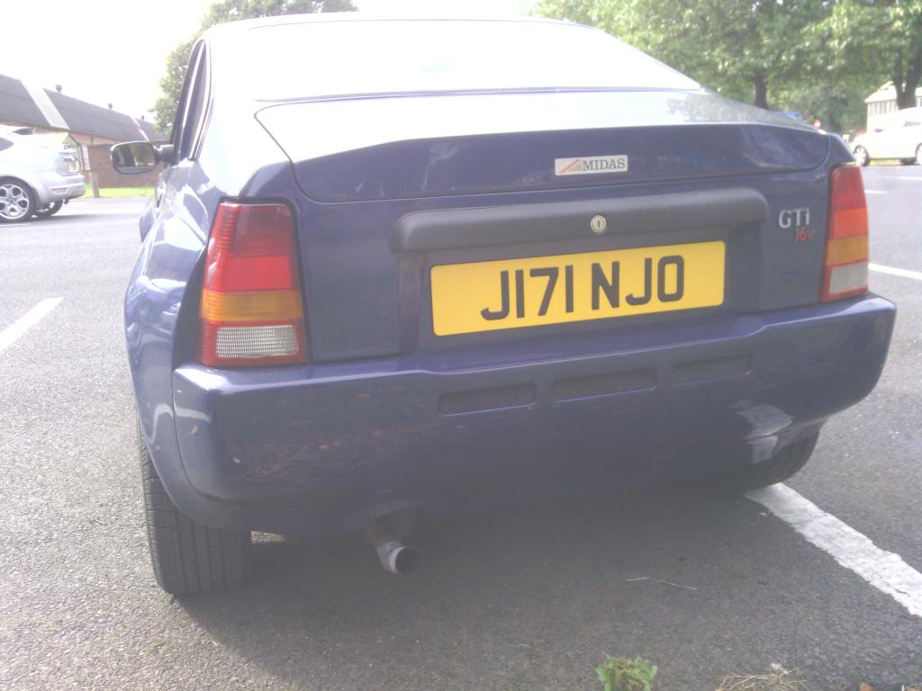 Dome some more, with the seats and carpet taken care of I wanted to sort the seat belts too, red isn’t my colour anyway 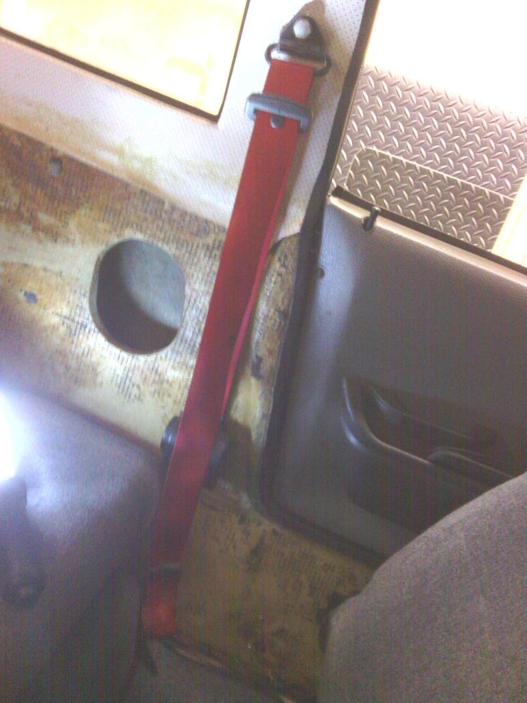 The big problem arose though because the lower loop bolt was well and truly seized into the plate inside the sill, I had already pop riveted in in place prior to trying to remove the bolt but that just got broke off, bugger So I decided to drill the bolt head off and knock the bolt and plate through the sill, it worked in my head however the plate must have been down in the base of the sill structure so it was bearing against the outer sill, so owing to the thickness of the inner sill (an impressive 16mm) it wouldn’t push through because it would have had to turn through an arc, Feeling a bit flummoxed I didn’t really see another practical was to resolve this other than to fill this hole in and utilise the second hole with a new captive plate behind each with which to bolt a single fixing point to from a 5 dr metro so this is what I did I got some proper seat belt spacers that total just over 16mm, thankfully they are a perfect tight fit into the sill hole 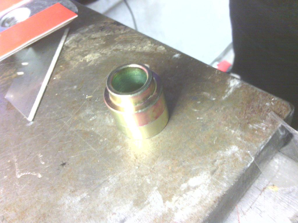 The remains of the old bolt cut down flush 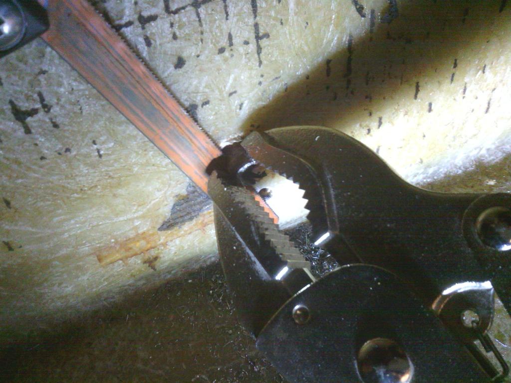 The old holes filled in with some gelcoat and some new speakers to fit the rear holes and with the exception of carpet the sides are done 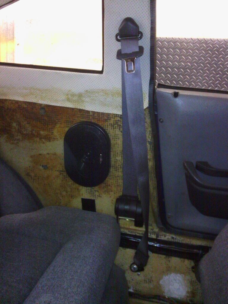 Then In preparation for fitting my new front shocks last weekend (which arrived but were mis matched ) I tested the water to see how much of a pain they would be to remove, which meant removing the headlights which in turn revealed some very scary looking wiring, the combination of poor or no in insulation to the many many joins (most along the same length of cable) and the sheer number of loose stray wires with seemingly no use was quite intimidating. First was the horn – well both of them It would appear that at some point or another the original horn mounted behind the front bumper has failed so rather than replace it a new horn had been placed further up the engine bay right in my way to access the gearbox and the feed wire extended to reach, then an earth tacked onto the neg of the battery, so with a new horn fitted back down the front and the original earth wire re-used that’s 1 loose wire taken care of and one of the multiple of ring terminals from the battery neg removed too. There then just followed a systematic strip down of all the wiring on the front of the car (ancillary circuits such as lights and fan etc., not engine related yet) and I dealt with the following Passenger main beam wired to the driver’s side main beam, wire re-joined and full power restored with a clean of the fuse terminal 3 extra earth wires that took different routes round the engine bay from the battery neg to the same earth point at the front of the car, the same earth point that utilised the main thick lead from the battery neg anyway so why the need for these is a mystery? – all removed Fan switch, the worst wiring I’ve seen in my life The pos feed was taken straight from the battery (thankfully with a fuse) to the switch, the wire from the switch to the fan motor was intact but only just And the switched live that should have powered the switch was just dangling around behind the headlight? Pos feed from battery removed and all new wiring installed, now at least I have faith the fan will work when needed. All in all it’s a lot of work without much to show for it but it’s a job that needed doing anyway , still more to do though 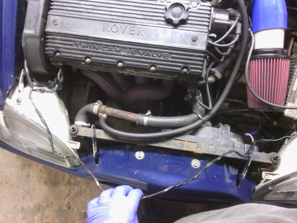 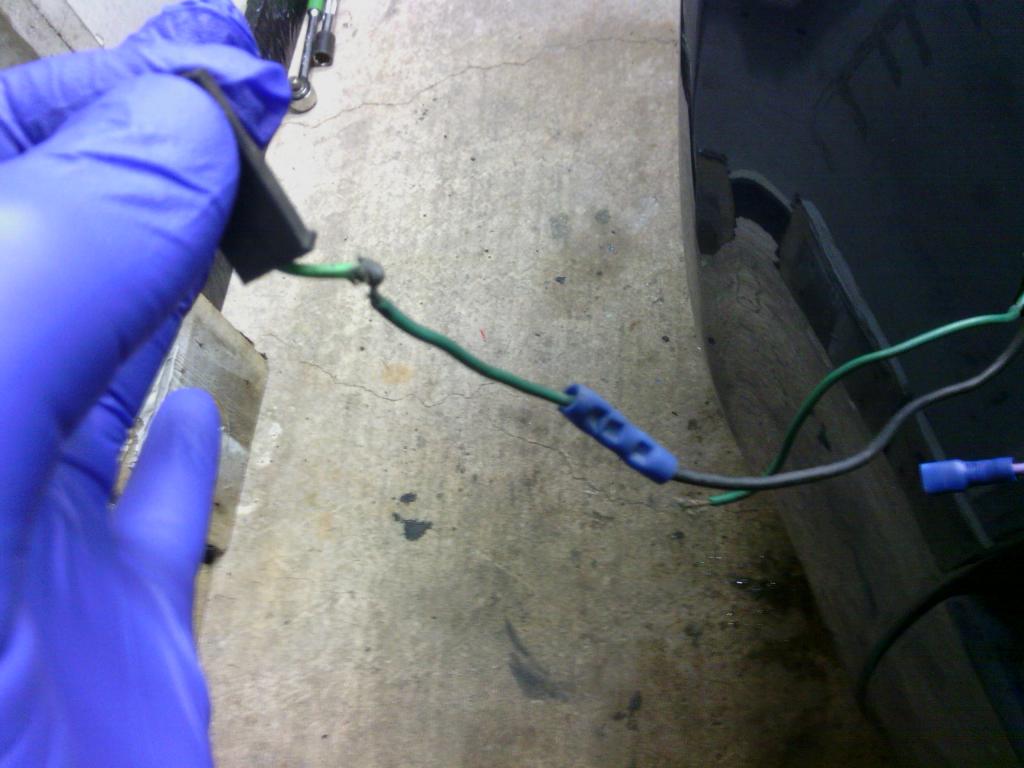 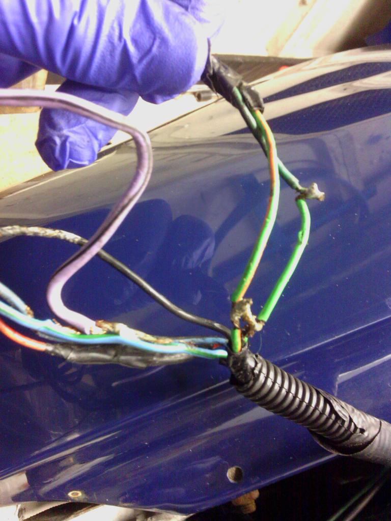 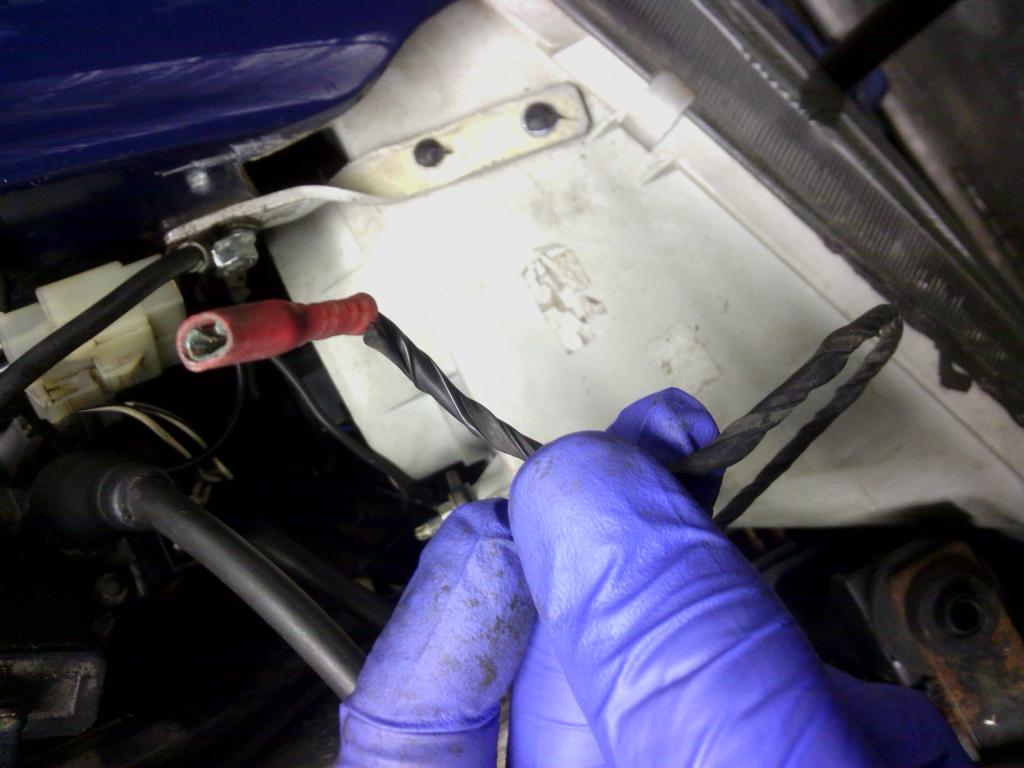  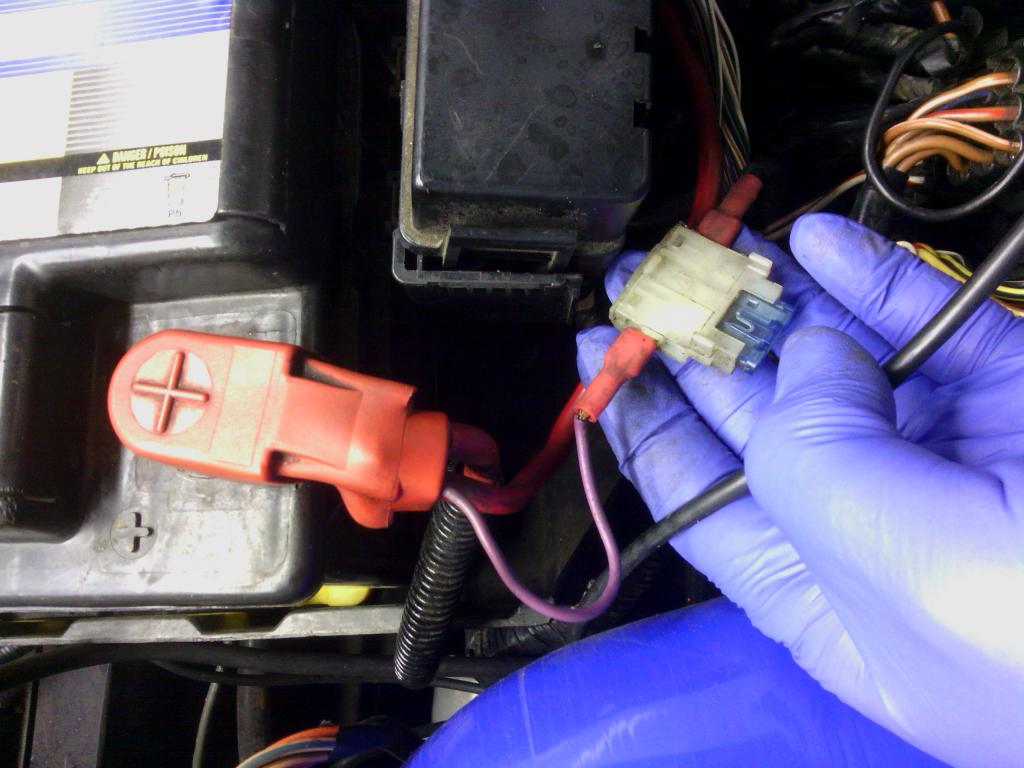 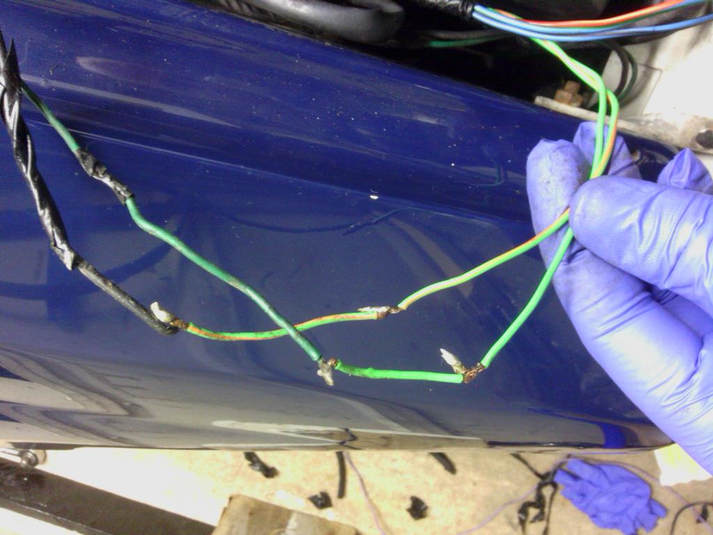 All new wires grafted in with new proper crimp on terminals, still work in progress as I'm waiting on new spiral wrap to arrive 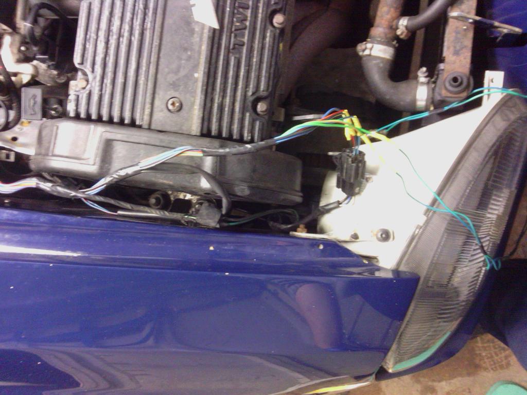 | ||
| Jin |
| ||
| Regular Posts: 159    | OCT 2014 Latest jobs The shocks were in a bad state, they squeaked all the time even when stationary (figure that?) so some new ones were ordered, once I finally received a matching pair I set to it, The “before” pic With the old shock out the way I could also find a few areas of voids in the fibreglass leading to pockets in the gelcoat, these were cleaned and picked out of lose material, then filled in with fresh resin to re-bond the fibres New shock in place You can see the problem, the old bushes had been cut down leaving them loose, the shaft had been chattering against the body causing the shaft to be worn away by the glass fibre Thankfully the body was perfect, good to see how tough it is Same round the passenger side, its good to see that despite to poor state of the suspension the front subframe is in very good condition Its was cleaned up and carefully masked and given a couple of coats of Dinitrol Then the splash liners were cleaned up and replaced with new clips This’ll do till I get round to the coilovers, I’ve also finished te front end wiring Ok so when I say front end its literally just the wires in front of the wheels but it had to be done Fan switch wiring and both headlight units rewired with new cables and plugs ans all spiral wrapped up. Ive also started replacing the subframe mounting bolts, the fronts are in a terrible state due to being sat in a bath of water each time the car gets wet More on that soon….. Read more: http://quantumforum.proboards.com/thread/971/midas-cortez?page=5#ixzz3rHllFUeN | ||
| Jin |
| ||
| Regular Posts: 159    | NOV 2014 Recent jobs and update - bit of a big one this so take your time Sub frame bolts First on the list was the sub frame bolts, due to the front panel cavity filling with water the bolts passing through to the sub frame were so rusty that drilling the heads off was the only option to remove them, so first job was to get them out 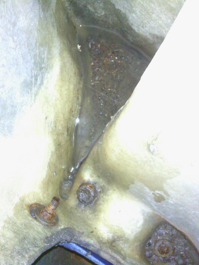 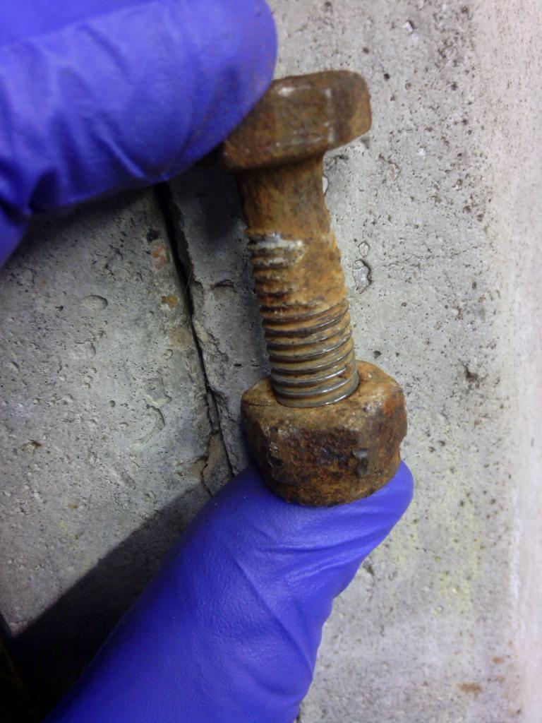 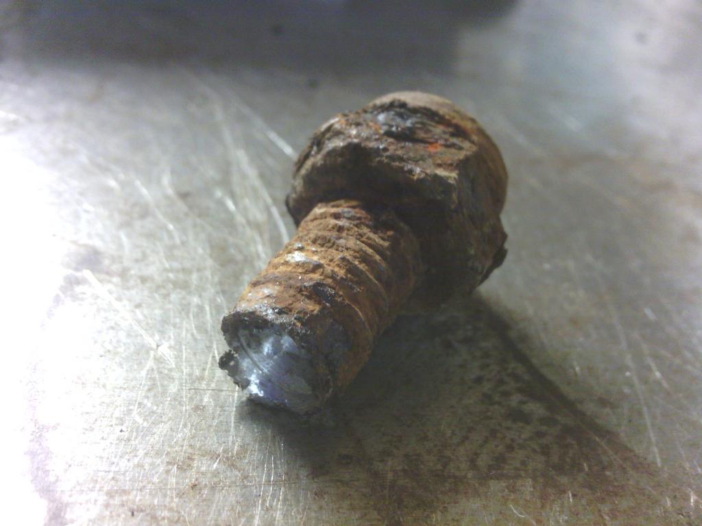 Then to find the replacements, here I decided to go for titanium and saved a few quid since these aren’t the fancy polished ones you see in most places, they are however a direct replacement for 8.8 grades in terms of strength, which I figure is perfectly acceptable since the bolts only go into fiberglass anyway, I’ve not chosen these for weight reduction just corrosion resistance since from above they literally sit in a bath of road water. 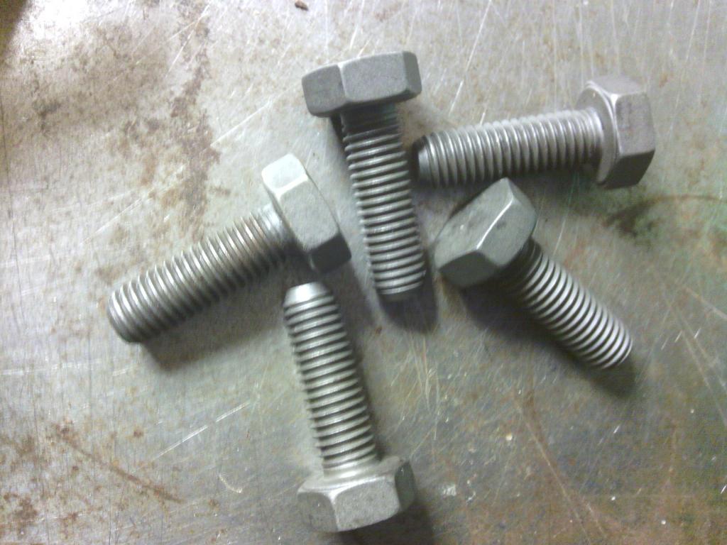 The bolts inside the car didn’t look much better 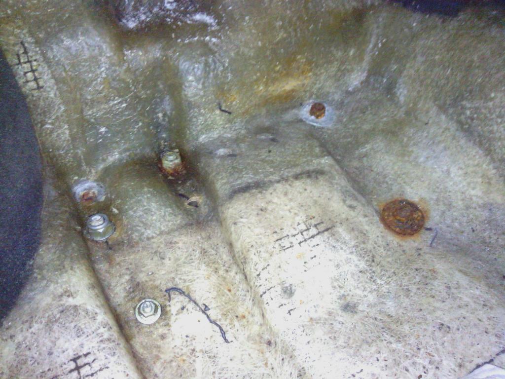 Second problem, both inside the car on the rear mounts and at the front mounts was the surface for the bolt head to sit against was far from flat, 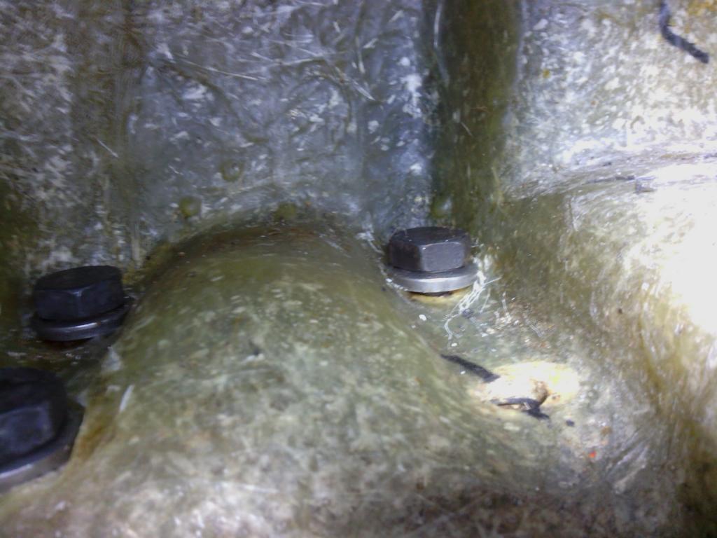 I estimate some of those bolt heads on the front were literally at 45 degrees in relation to the fiberglass surface and as a result the subframe bolts were only clamping down on point contacts on all 4 corner sub frame mounts. The options considered to rectify this was to file the bolt heads to match – tricky and a bit of a bodge. Make tapered washers – again tricky to match the angles perfectly but will also put a side load on the bolt head as the 2 tapers force together again not ideal, So I opted to machine the fiberglass instead by counter boring the top surface, now before you all recoil in horror I did take many measurements beforehand to check this was the best option and made the following points The fiberglass in this area is massively thick anyway – over 12mm The underside of each hole (gelcoat side) is flat to at least a 30mm diameter round each hole, it’s the top face that has become blurred due to multiple layers of matting so all I have done is reduce the excess matting down to the same thickness as that of the thinnest (remember still over 12mm) portions of the fiberglass and I’m only cutting a 20mm diameter counter bore. so just technically truing up the uneven surface removing out the minimum of material, I did this by mounting a 20mm O.D grinding bit in to a 10mm bolt cut down with a 6mm hole drilled down its length then cut down 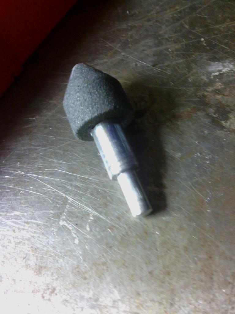 with this passed through from the top and fitted in the drill chuck from underneath and pulled down the grinder gently removed the top surface just enough to flatten it off 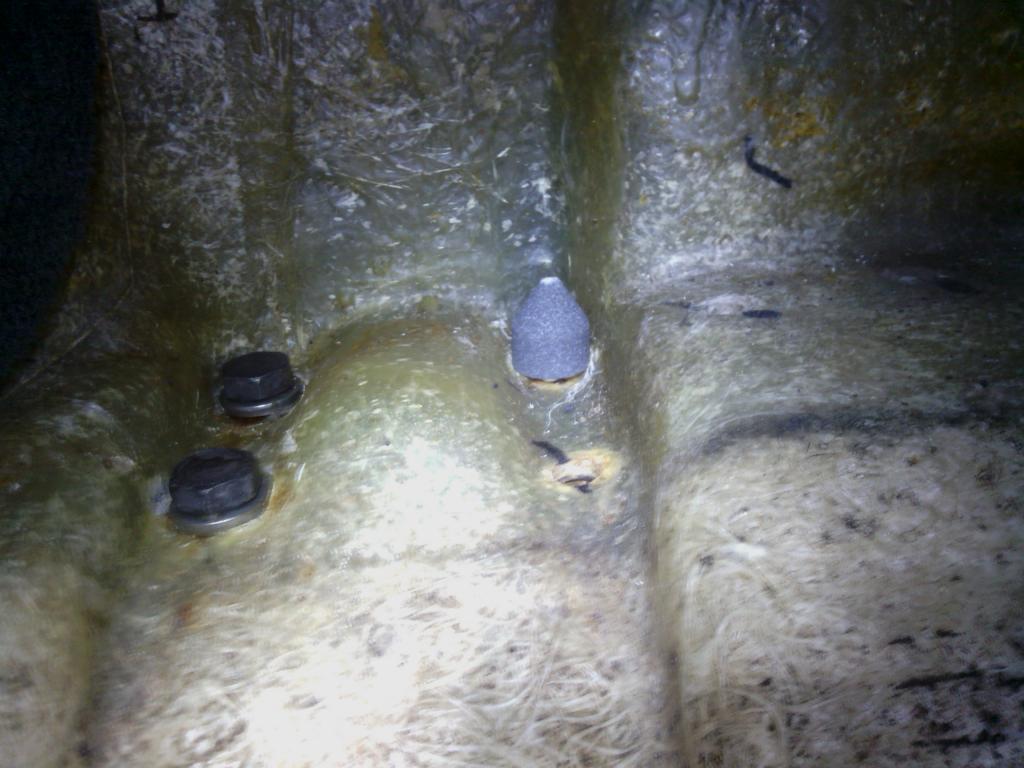 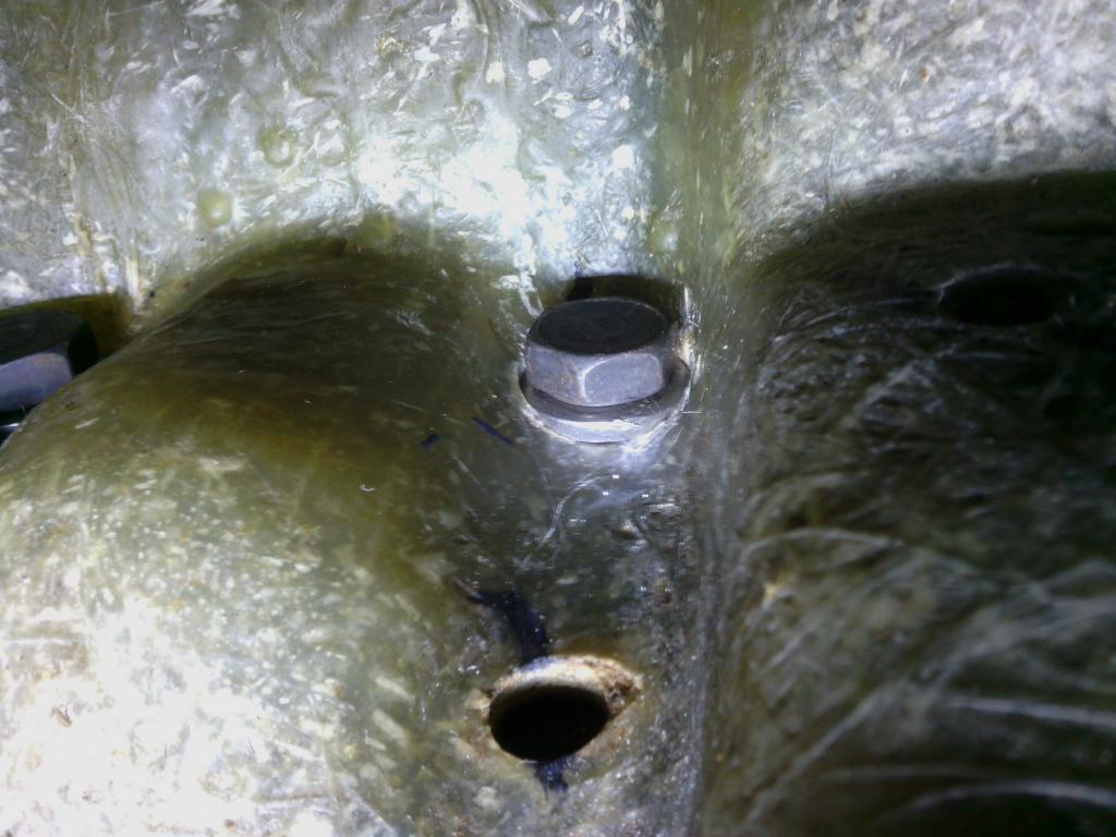 All done including the anti roll bar mounts 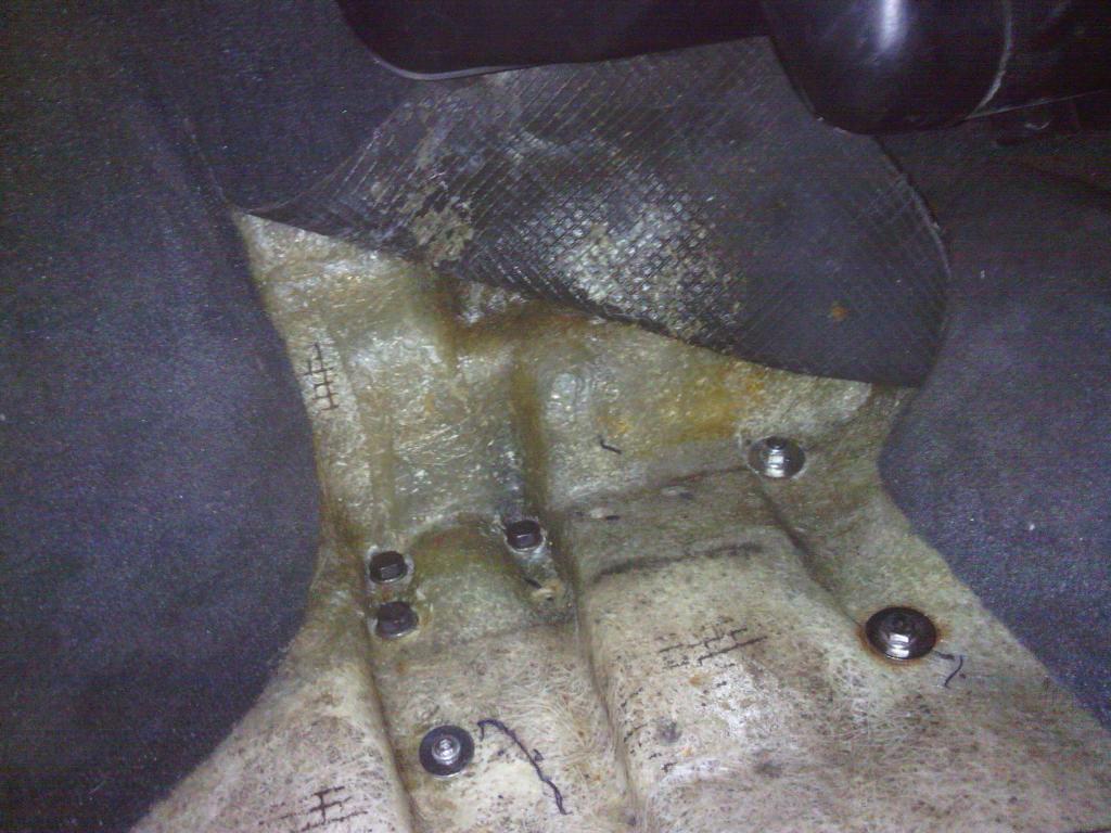 then for the front bolts where the cut-outs were deeper I used 10mm thick stainless spacers instead of washers 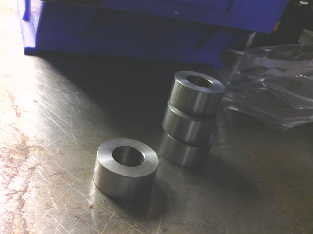 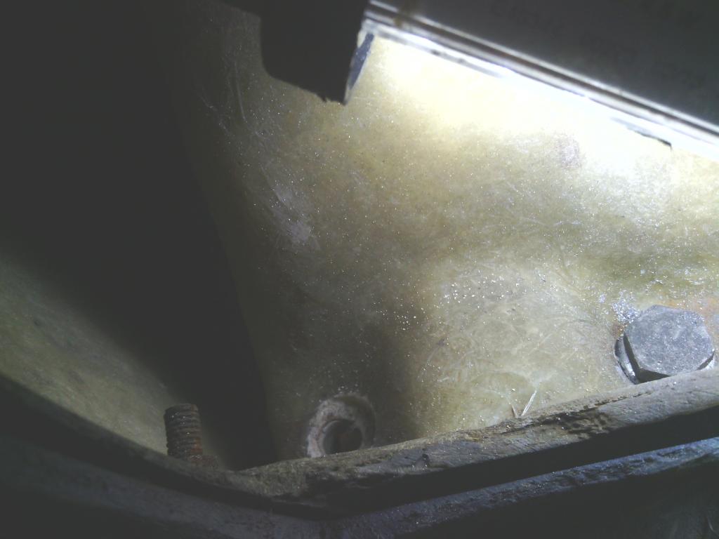 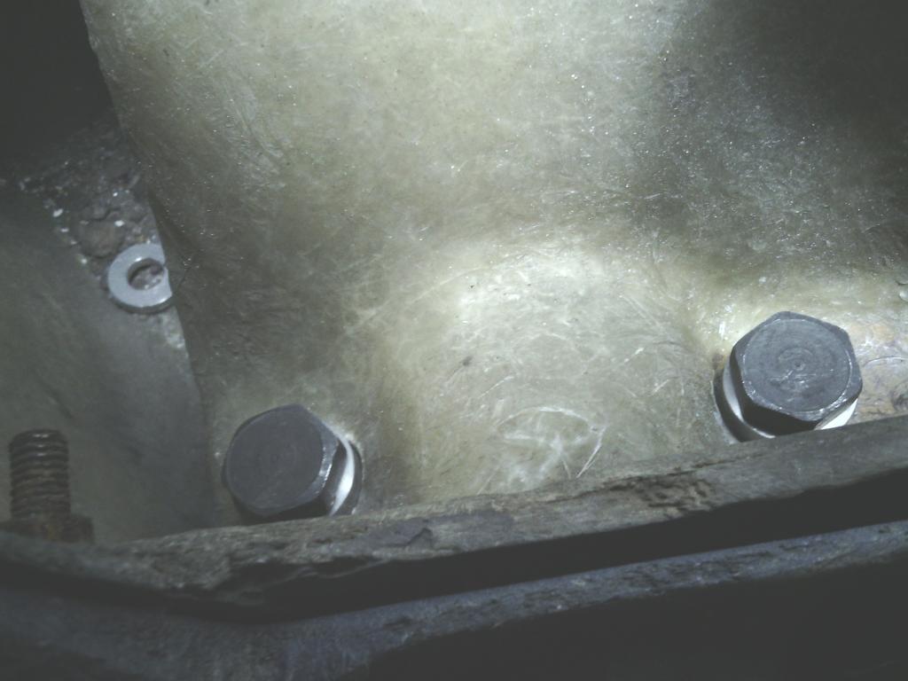 since they won’t dish in and raise the bolt heads up enough to grip with a socket, and for the inside on the floor where the discrepancy wasn’t as bad I got some 4mm thick 20mm O.D M8 stainless washers and reamed the hole out 10mm, these will do fine and wont lift the carpet as much in the footwells. 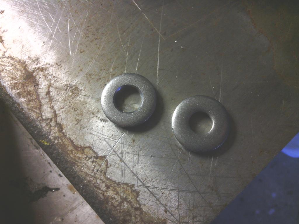 For the underside of all mounts I got some M10 titanium flange nuts which did come in a shiny finish which I suppose won’t hurt, So although the car has lasted nearly 20 years, now I know the bolts won’t rust away like the old ones did. So if I ever have to remove the subframes it won’t take a week to unbolt 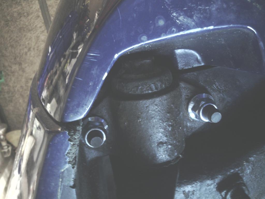 Engine earths and wiring An ongoing job that is getting better and better as the weeks roll by is the general state of the engine bay wiring. The 2 branches or loom that ran down each front inner wing had multiple issues ranging from crappy soldered joins – crappy un-soldered joins(?!) lengths of loom that were far too long and had excess loom taped up and stuffed into corners and a total lack of any cable supports whatsoever resulting in the loom branch running down the driver’s side wing being only supported by resting on the (very rusty and rough) hydragas unit causing the outer loom tape and strand insulation to wear through 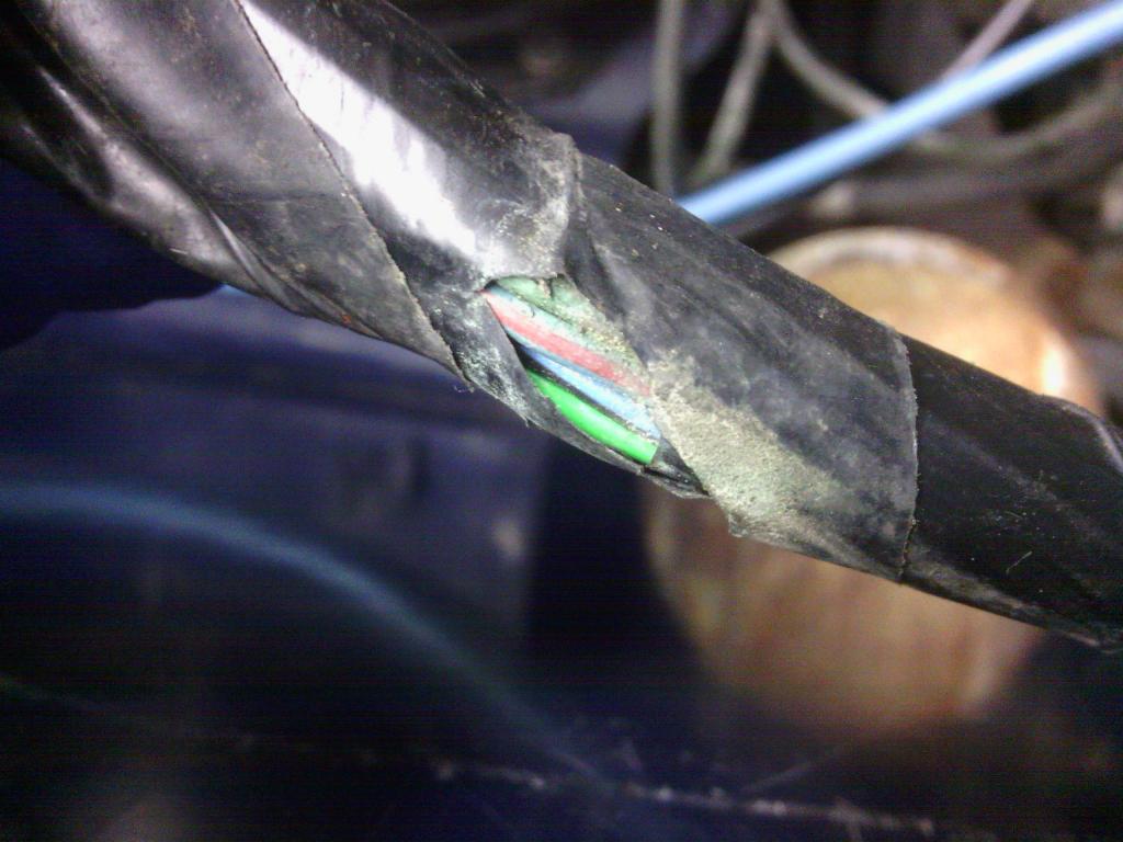 About a few months use away from a short and potentially a fire… 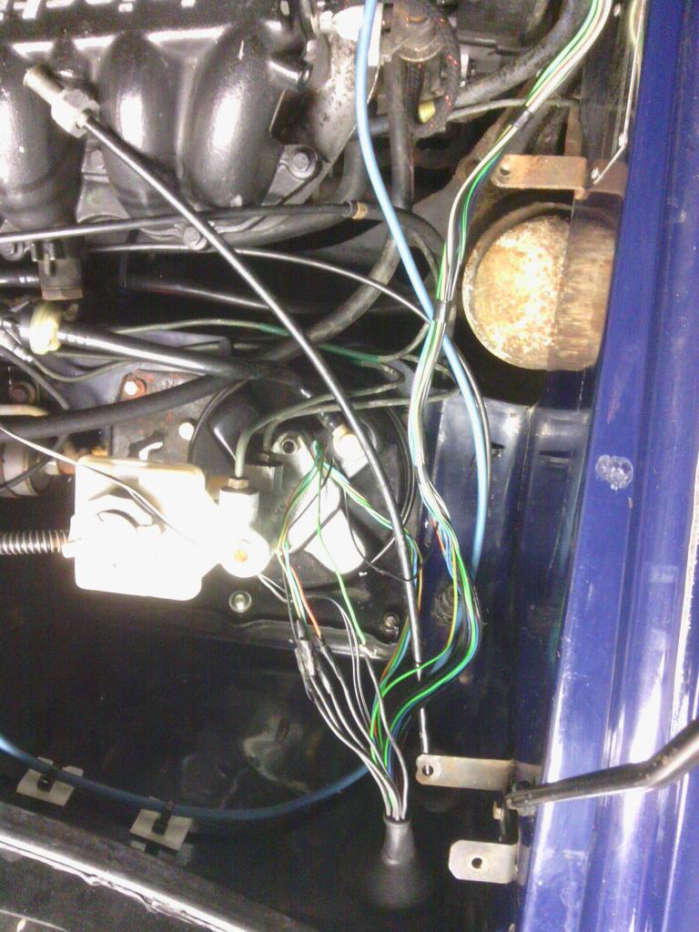 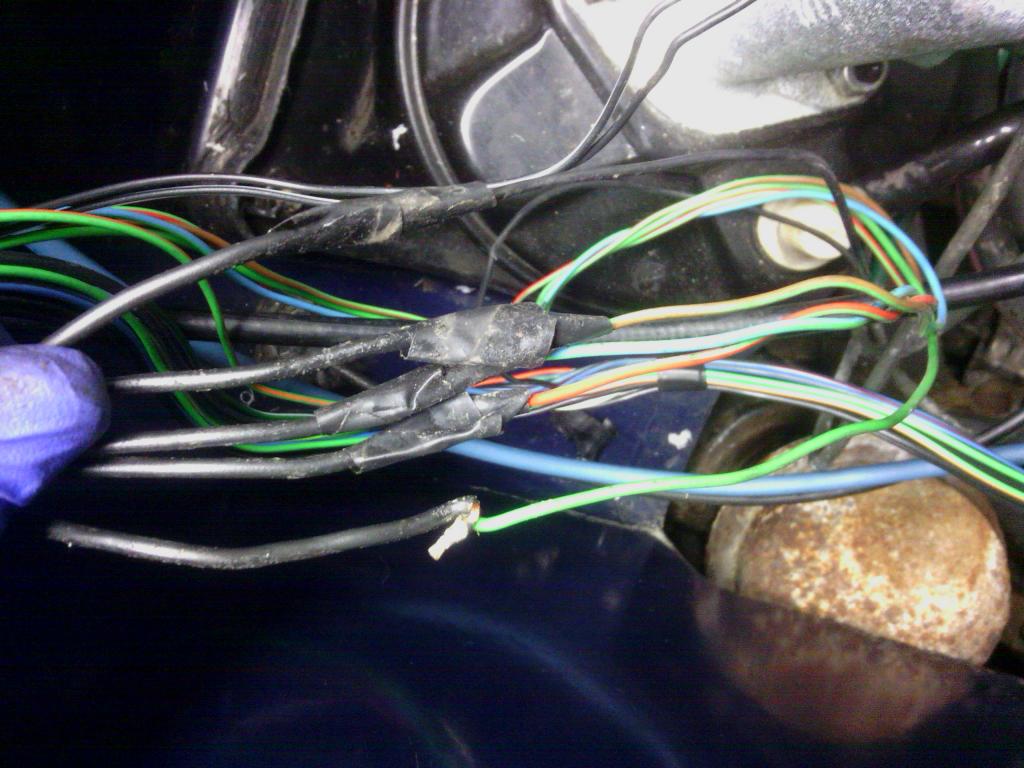 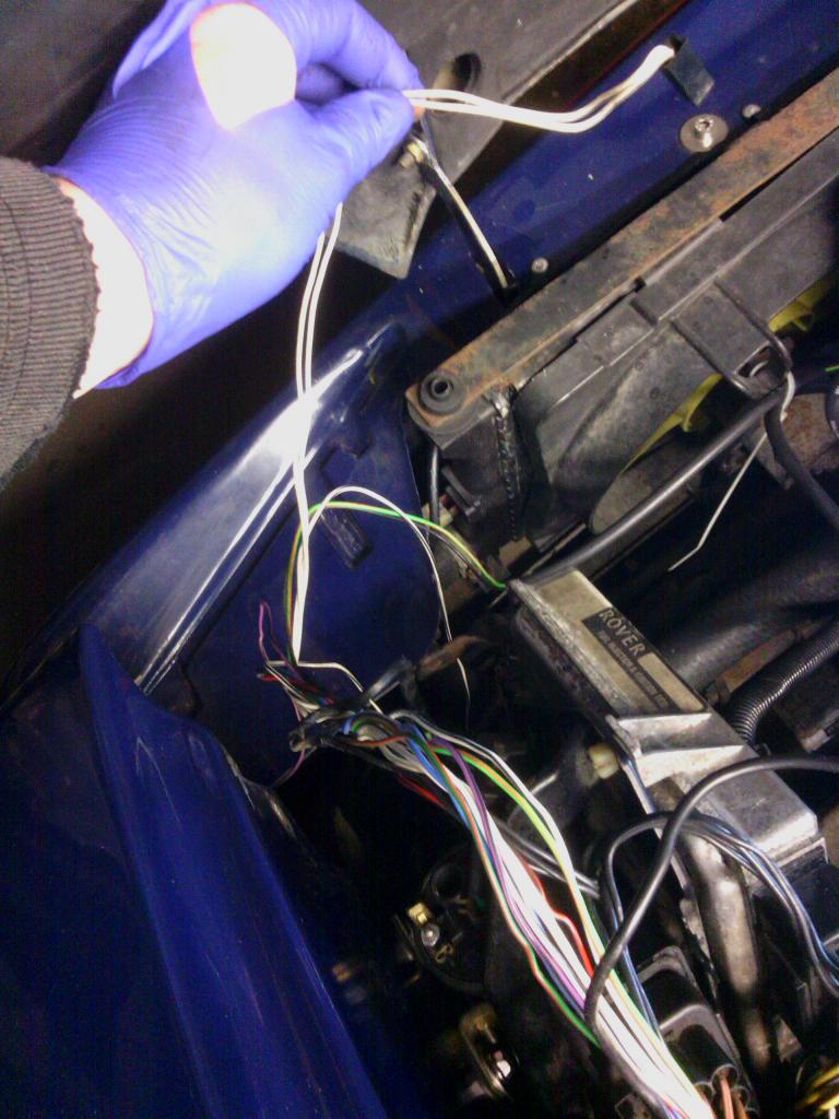 So all excess loom was removed including the redundant rear screen washer pump and its associated plug and wiring from the fuse box, the plug came in handy to replace the front indicator plug that had been cut and taped into position, All joins now soldered and 2 layers of heat shrink, I even removed this thing 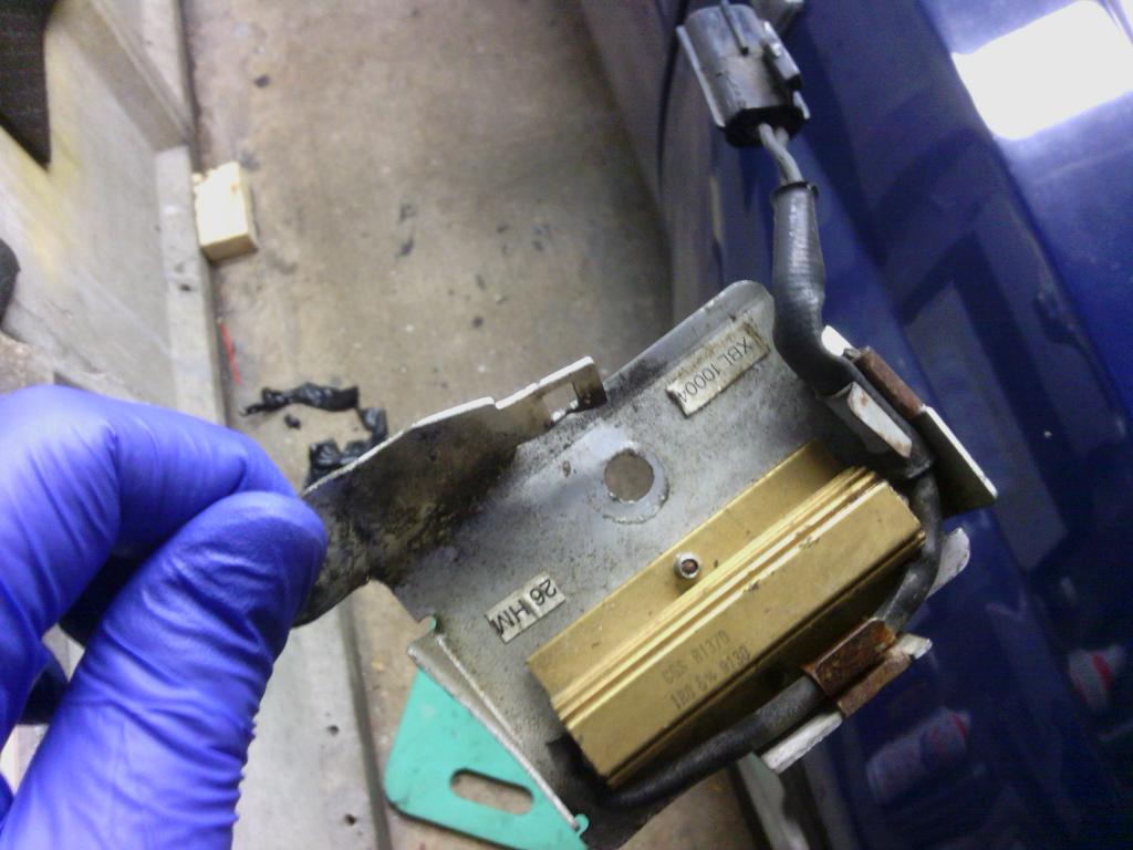 Dim dip resistor thingy, ive read about 4 descriptions of what it should do and to be honest non make sense, if I want my side lights on ill put my side lights on, If I want my dip beam on ill put my dip beam on, If I want my dip beam bulbs to look dim and dirty and like they are burned out I would fit some duff ones, but id rather keep the 2 separate thank you so that’s gone in the bin too with no ill effects. I also decided to amalgamate the earth connection points on the rover loom to just terminate at a loop tag rather than a block connector and then a loop tag, the less joins the less chance of failure 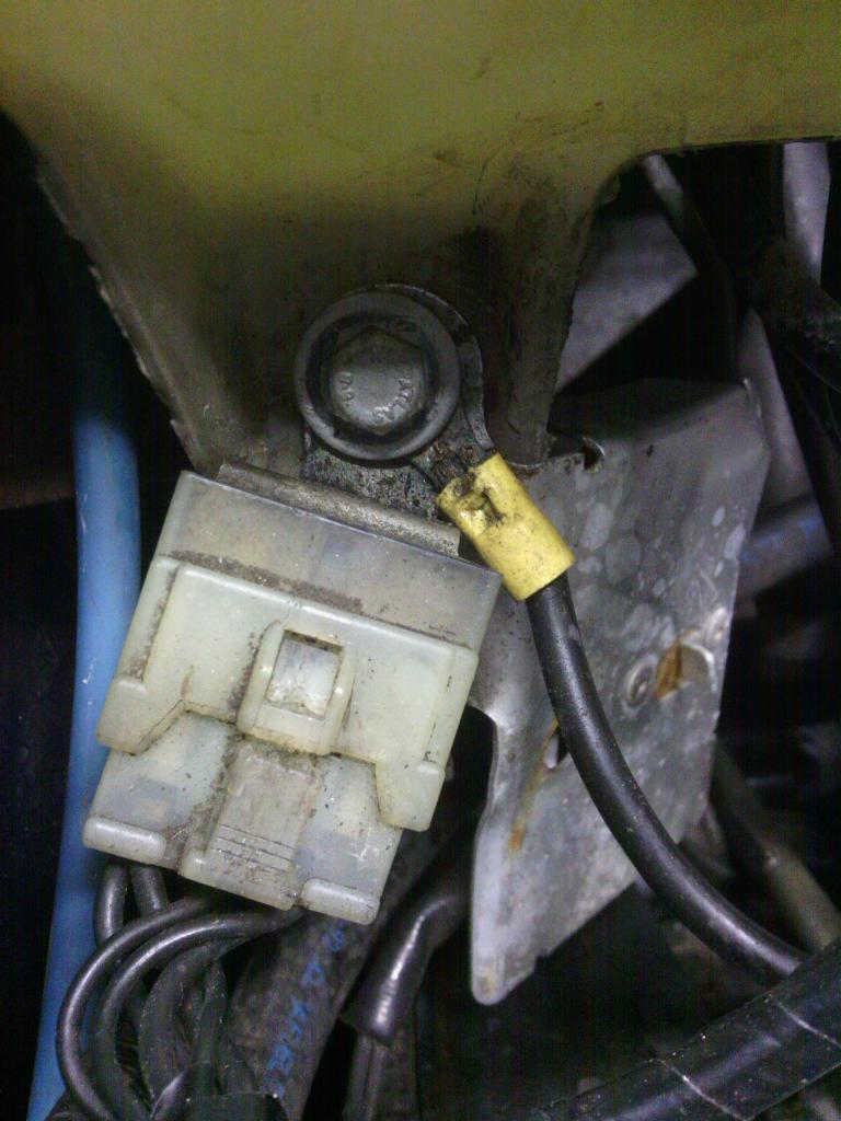 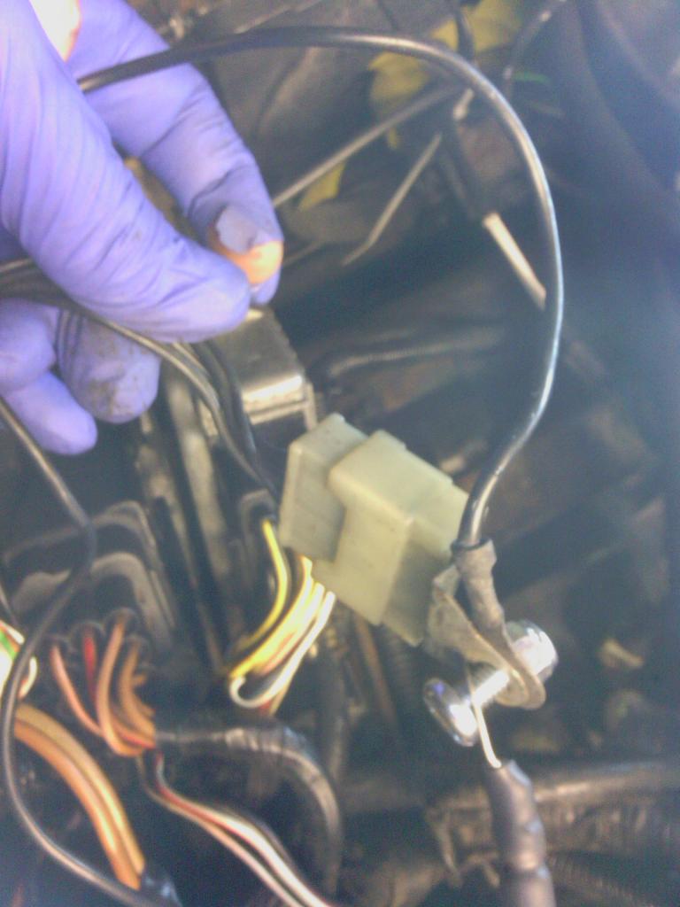 The entire loom now spiral wrapped and P clipped into place 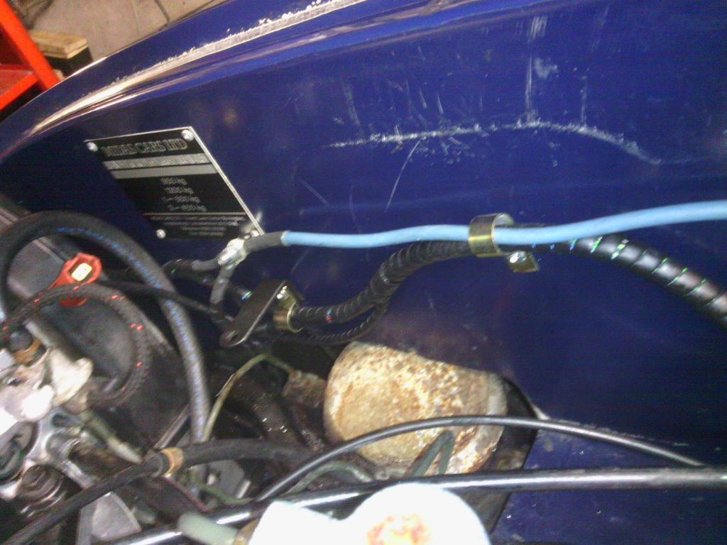 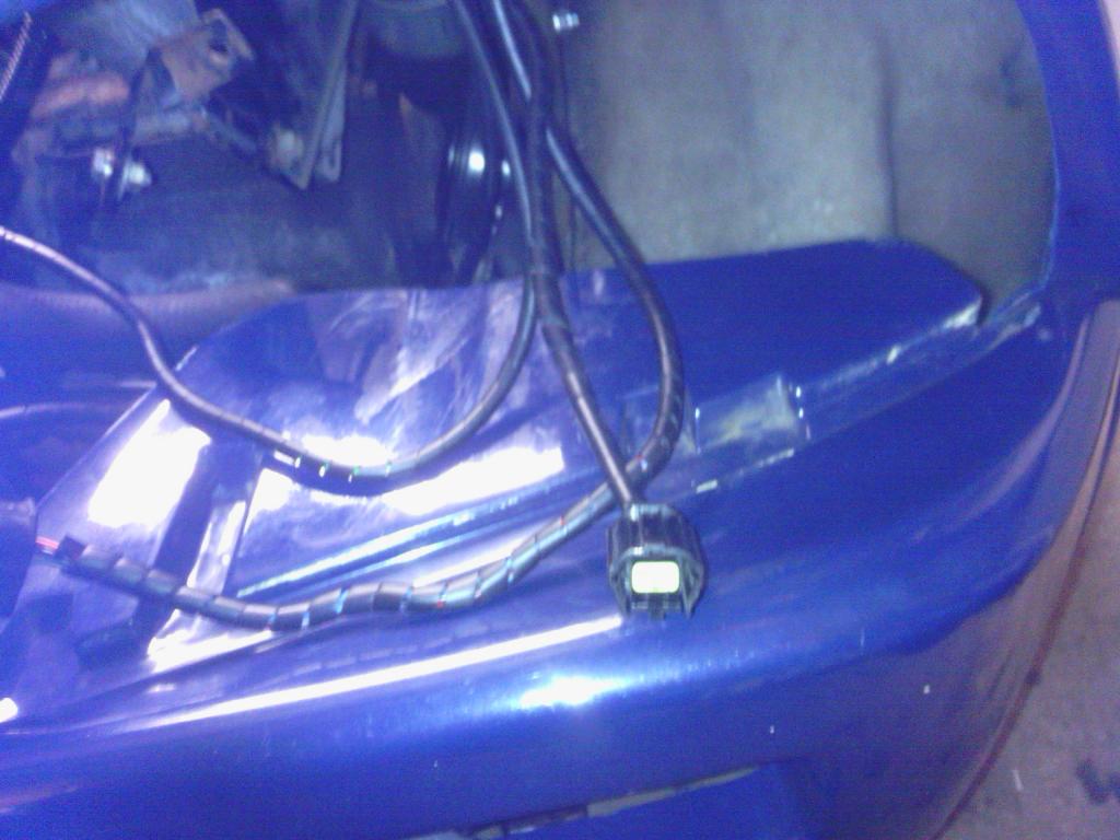 The whole effect is much neater and inspires more confidence. Especially considering the mess that was there before  I even found a chock block connector coming from the main fuse board in the engine bay, a little shocked at this discovery I thought id find out what it was powering before repairing, thankfully it wasn’t anything too important just the main feed to the ECU and associated engine bay sensors…… 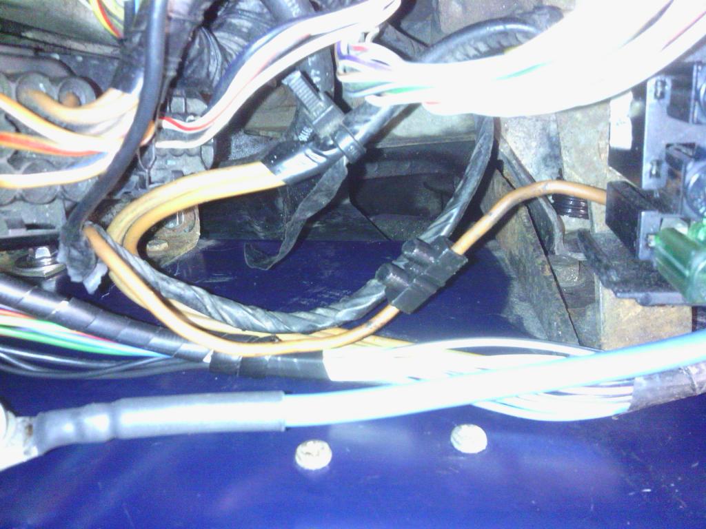 That taken care of I even gave the washer bottle a clean out as it was rather manky inside and out, I know you can clean things like this out with rice and soap by giving it a good shake but we had no rice so I used pasta twists instead, well pasta is the same as rice anyway in as much is its what you eat when there’s nothing better to eat left in the house, so on that basis and a dash of bleach inside (and all over my jumper) the bottle came up like new, a good tip there 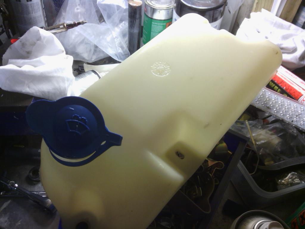 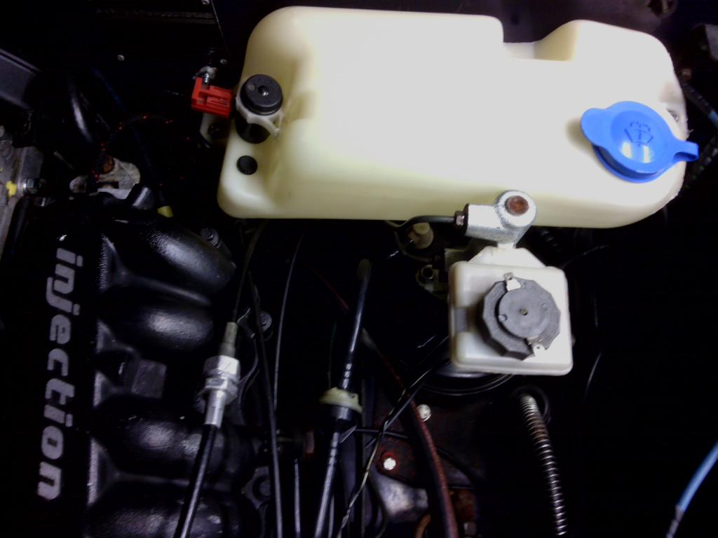 The earths were a cause for concern, there appeared to be no logic or reason as to what got earthed where and how, for example there was a total of 3 separate wires running from the Neg of the battery to the passenger headlight mount bolt (used as the only earth point for that side of the car?) and yet each took a different route round the engine and engine bay to get there, the slightly bigger cable sending the earth wire from the passenger (battery) side to the driver’s side was not supported in any way just wrapped around various hoses and pipes on its way, something had to be done so I ripped it all out 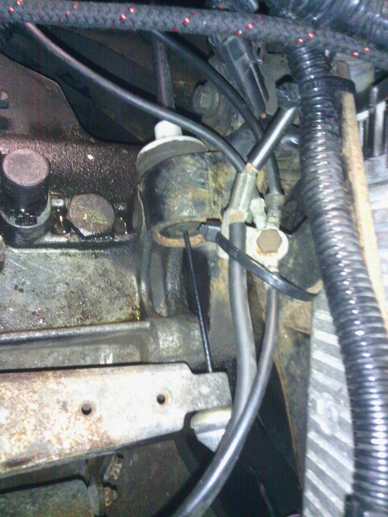 Assembled a collection of new earth cables 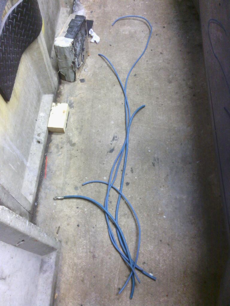 I bought some of the best cables I could find http://www.klaceycables.co.uk/shop/product/15/uniefglas-efglas 5 in total, the 4 thinnest are as thick as the original and the 1 thickest is twice as thick still, earths are very important as I’m sure you all appreciate, the 4 smaller cables feed the bulkhead where I’ve made an earth stud to feed all the rear of the car power and 2 go down each inner front wing, and lastly the 4th goes round to a convenient tapped hole on the far side of the cylinder head, 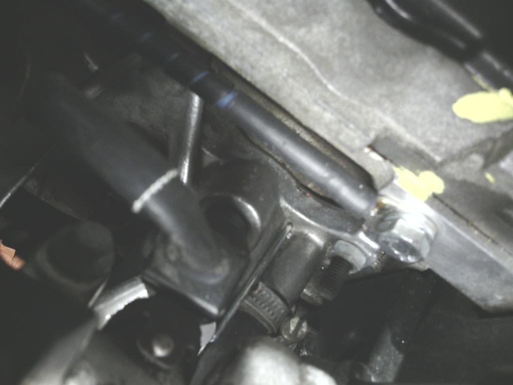 the 5th and largest goes to the gearbox as per the original, all 5 cables were soldered into a new battery clamp making one solid connection 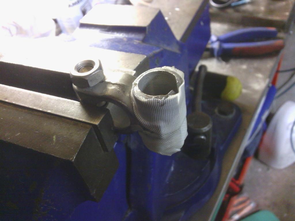 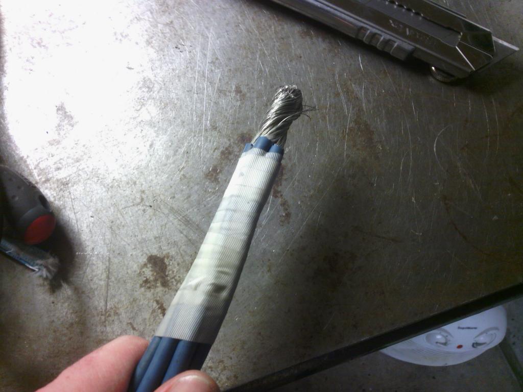 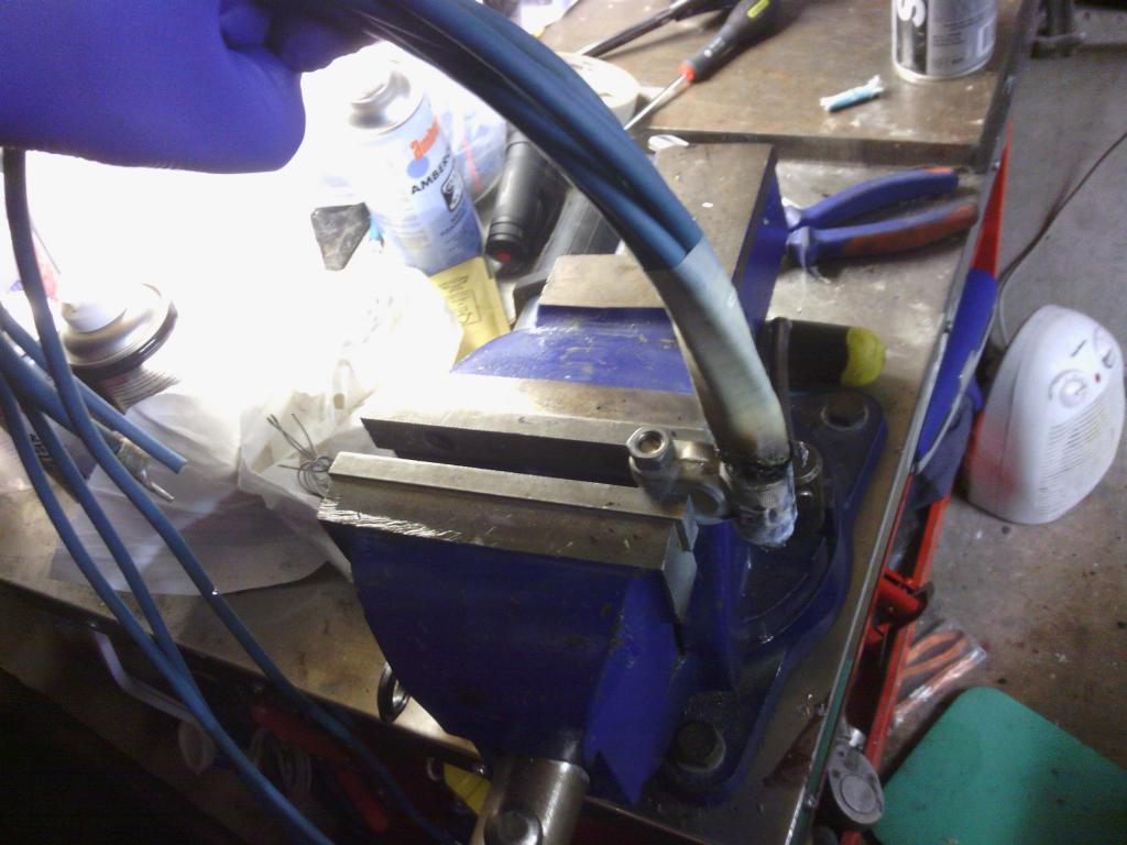 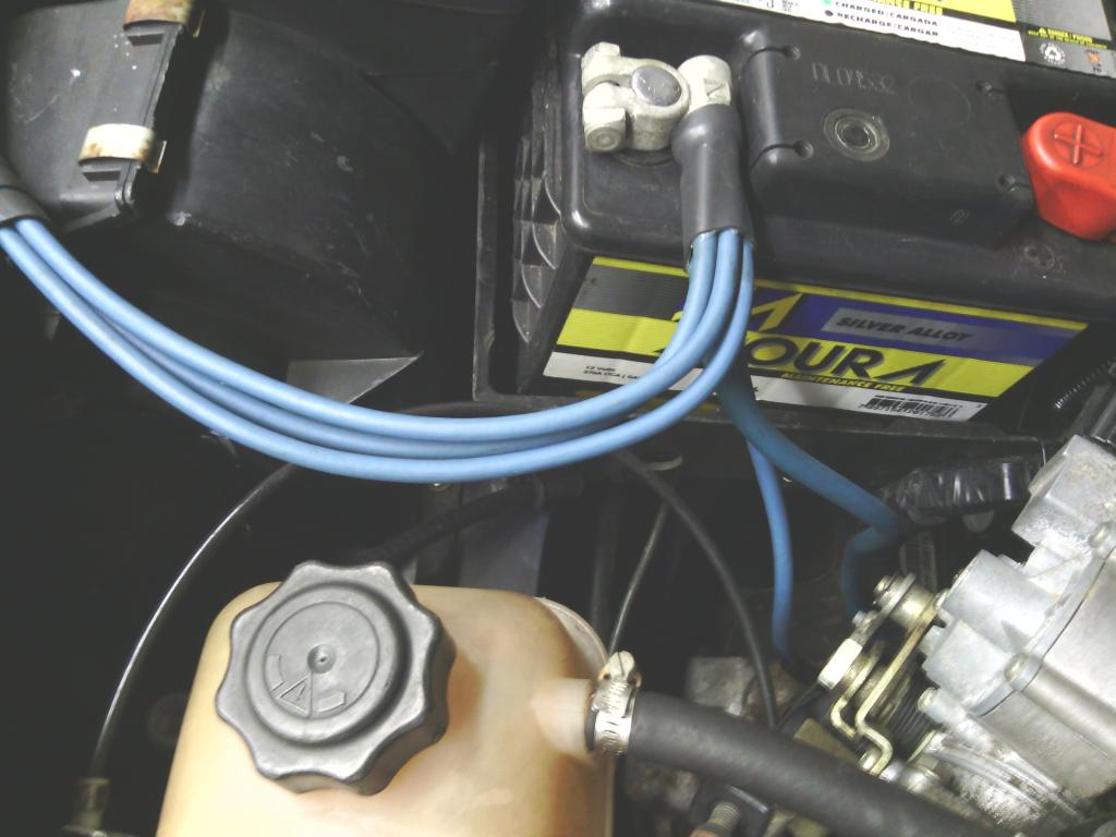 All cables tucked up neatly 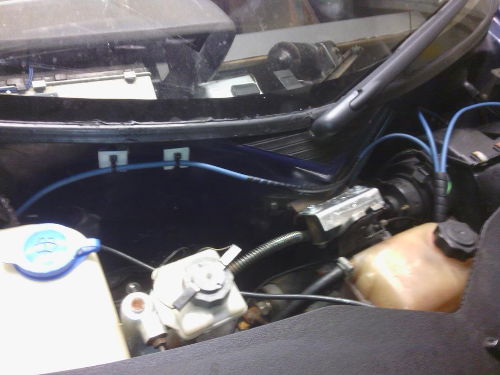 I hate the thought using of fixing bolts as earth points with 4 or more loop tags on being used, just looks like trouble waiting to happen, so I made some bus bars out of 4mm thick brass with M6 csk brass bolts silver soldered in, once riveted and bonded to the inner wings the result looks neater and has a spare stud on each for future use.  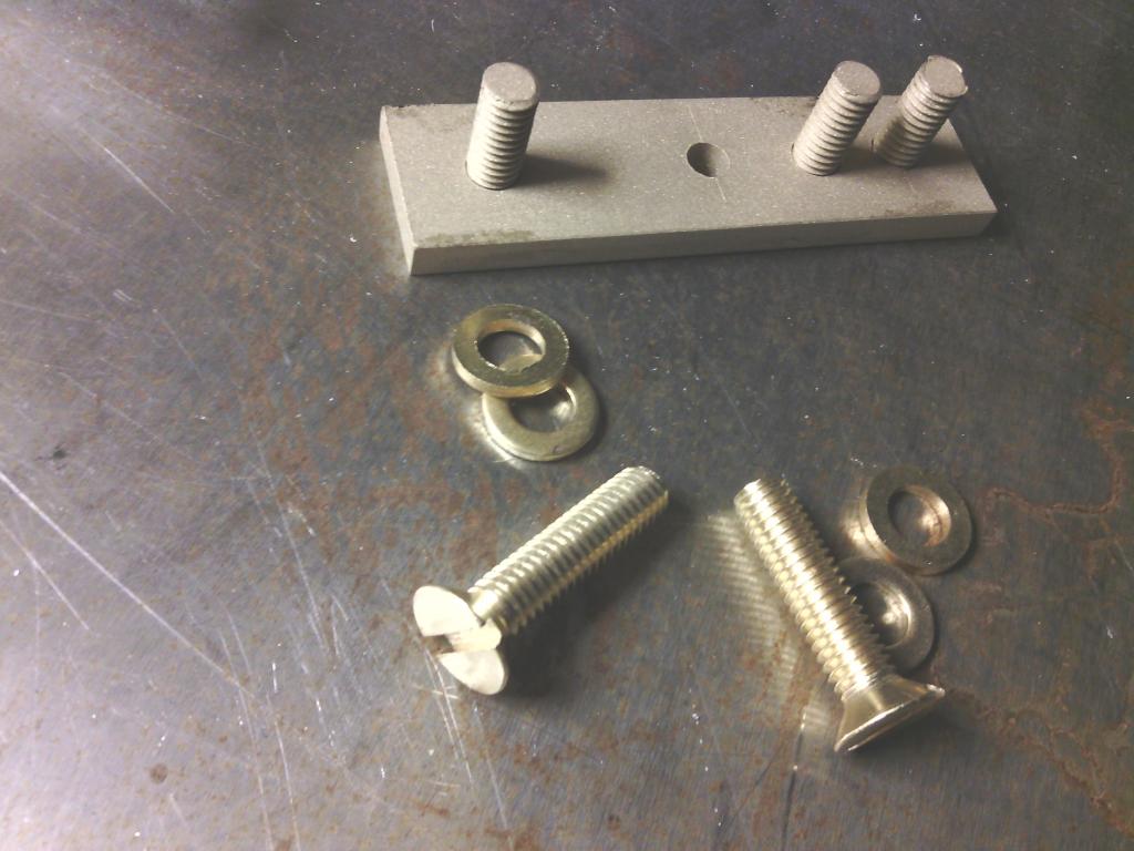 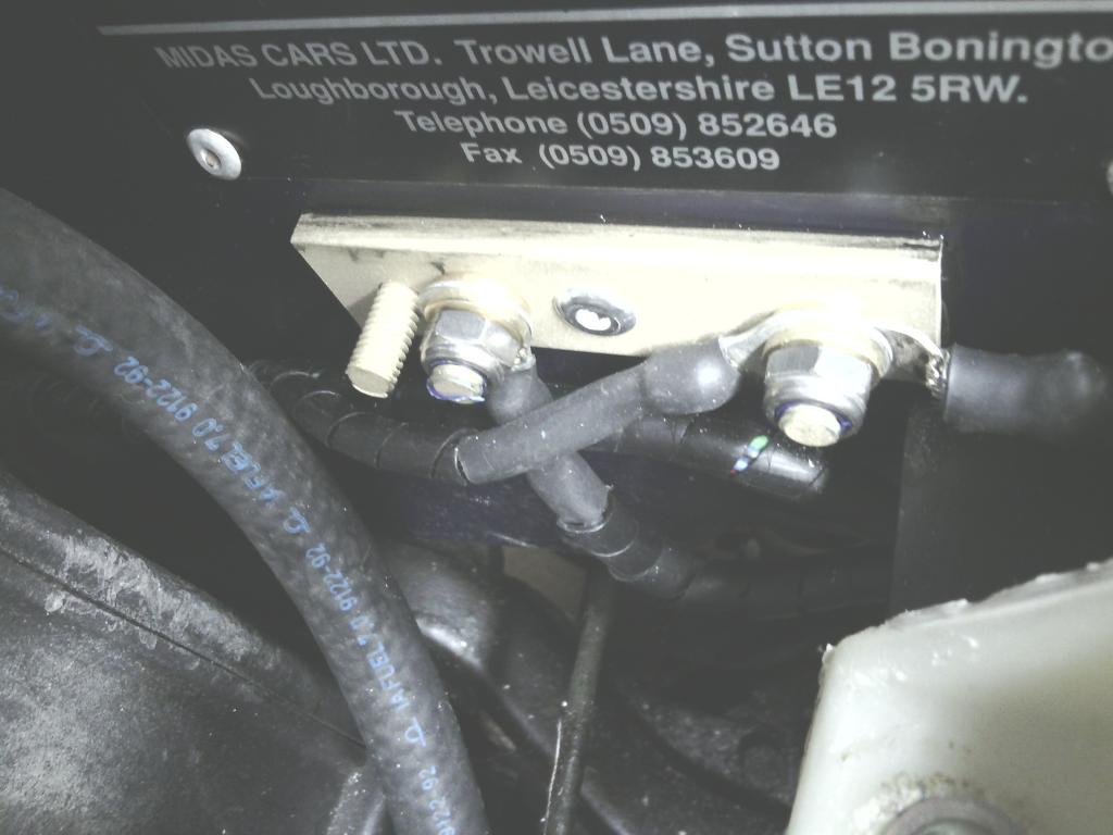 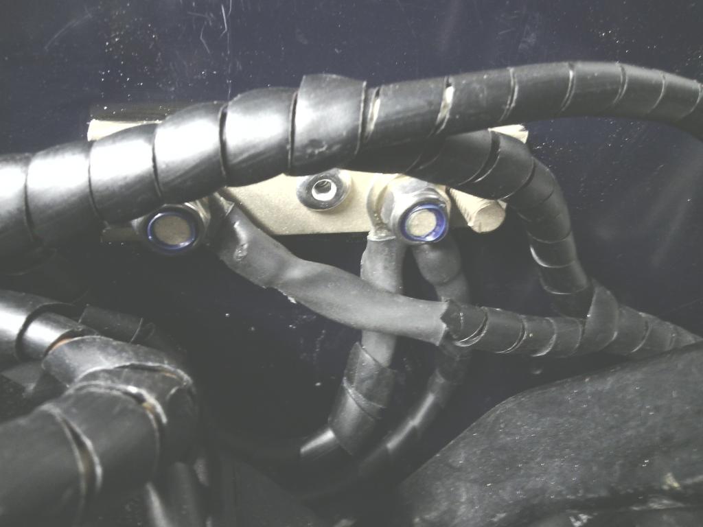 I even treated the new distributer low tension cables to a new distributor 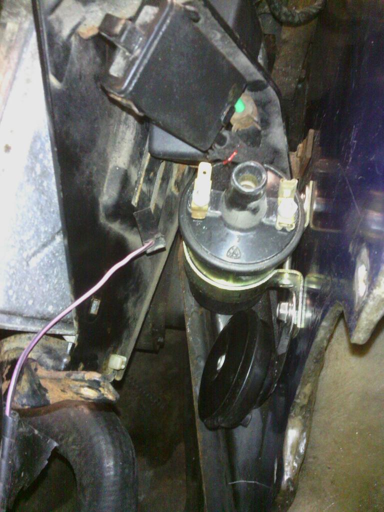 All the smoke now stays in the wires here it should ? Front grill Ever since I bought the car I wanted to change the front end somehow since it tends to look a little “pouty” and the front end too narrow overall. I had to pull out the mesh anyway while I was tending to the sub frame bolts so now was the chance, after much thinking around and doodling I figured my best option would be to fit a horizontally slatted grill in all orifices to unify the look and hopefully blend the 3 separate small grills within one bumper to look more like one larger grill broken up slightly with bits of bumper, if that makes sense? After eyeing up many front ends in car parks (I looked at front grills on cars too) I came to the conclusion that mk5 Vauxhall Astra facelift lower bumper grills would do nicely, mainly because its slats run horizontally and the front goes to a point down the centreline a bit like the Midas so hopefully they will match. (I really have got to stop bolting bits of Vauxhall on my car because one day it may just turn into a……. …..I cant say it – the thought is too scary.) I I ordered a plain cheap copy grill off ebay to butcher to see 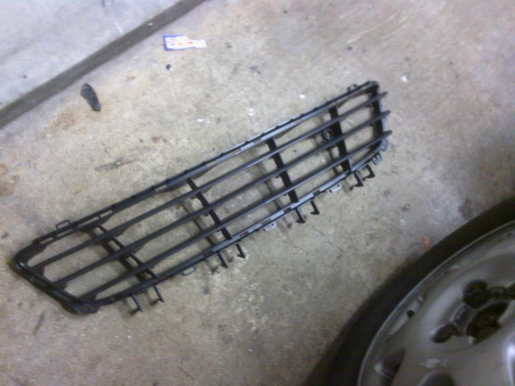 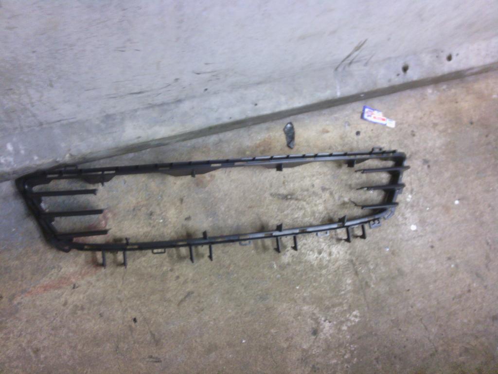 Works a treat but these need to be chrome to provide more definition to the linier effect I require so 3 brand new genuine Vauxhall grills were ordered (£ = don’t ask) and each one butchered to provide me with the grill of my dreams, 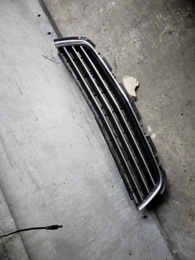 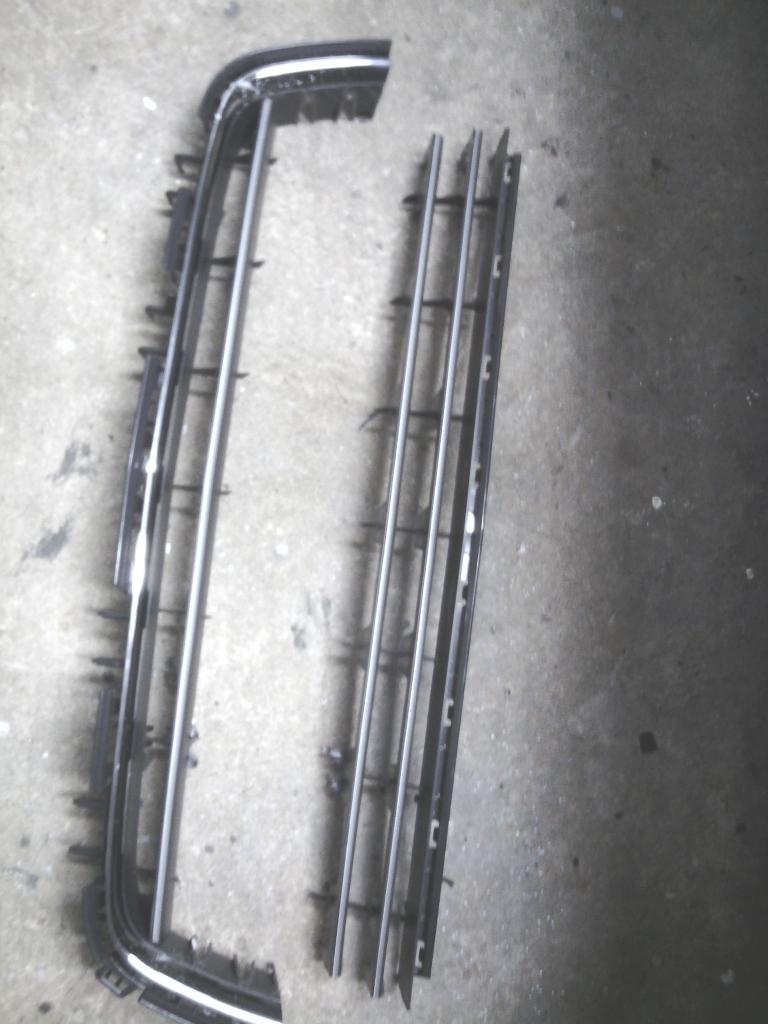  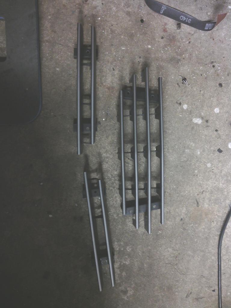 the standard Vauxhall grill has 3 slats and I did try it in that configuration but it didn’t quite look right so I chopped up 2 grills to make a 4 slatted grill, the sections were bonded to some angle profile plastic. 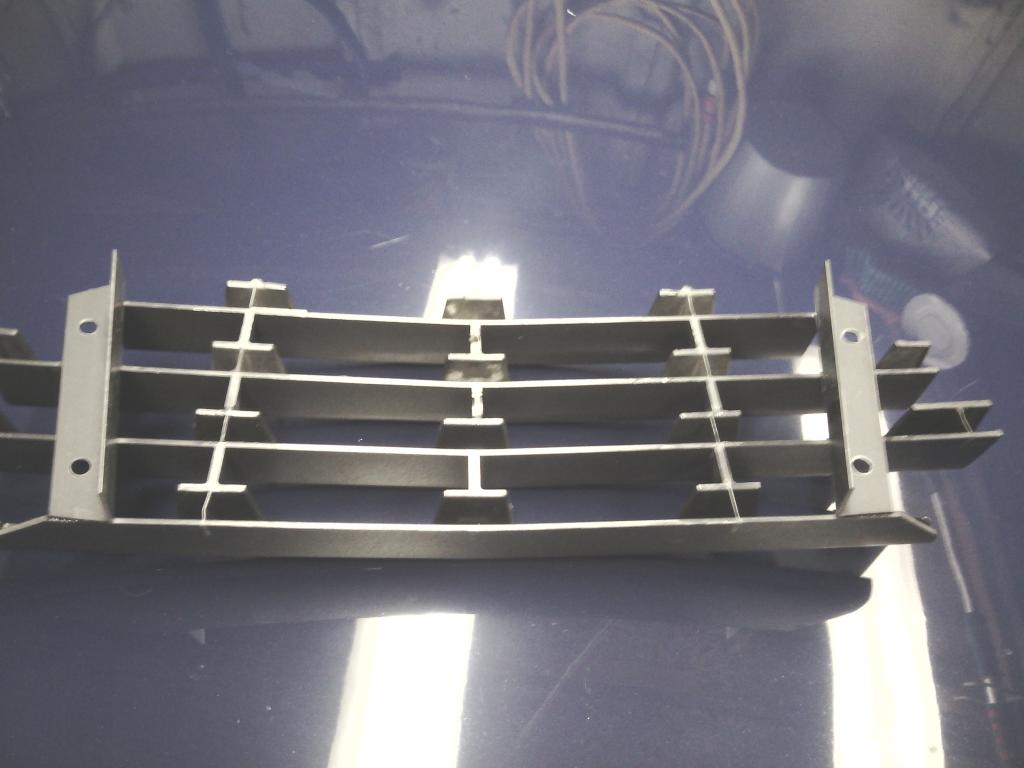 And I made some ally brackets bonded on inside the nose cone with M6 tapped holes so the grill can be removed again without it being bonded on – nice 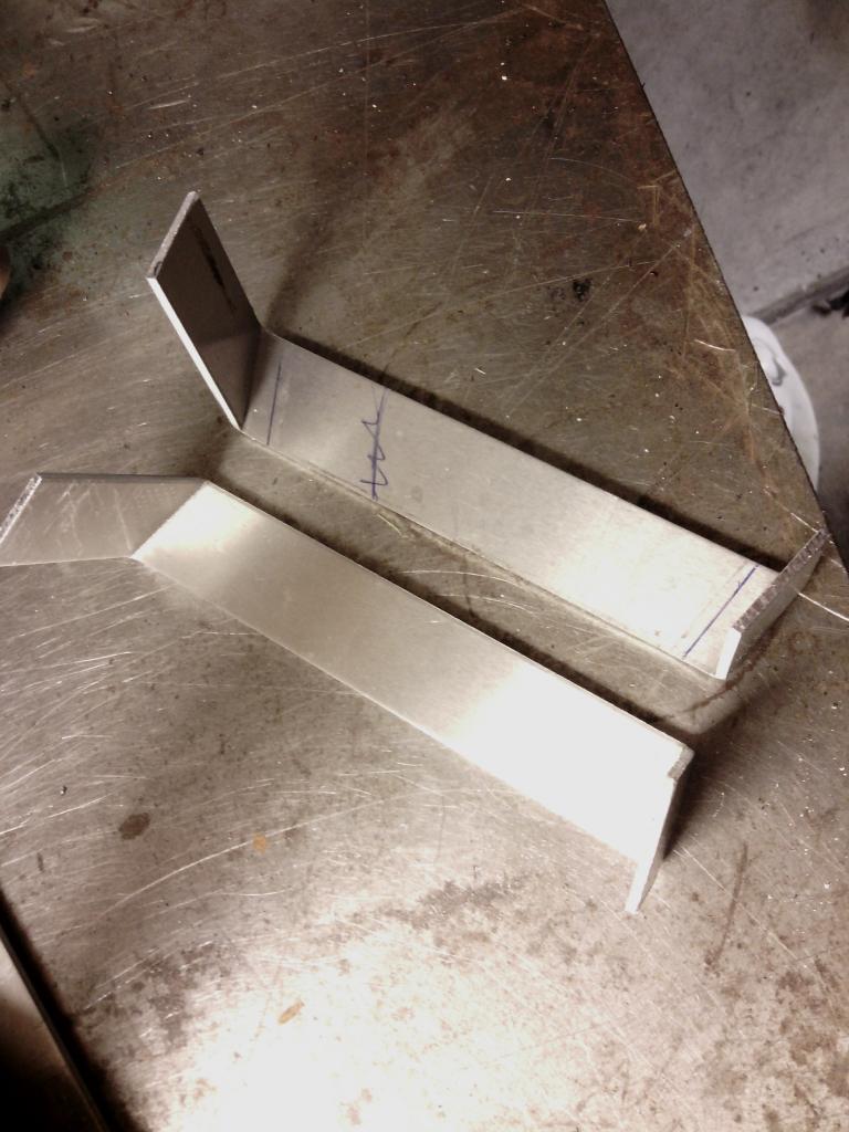 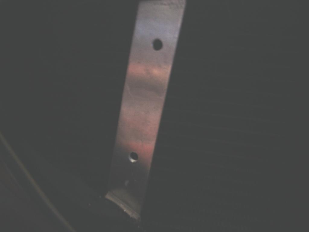 The side grills were done in the same way with angle plastic and ally brackets bonded to the nose cone, 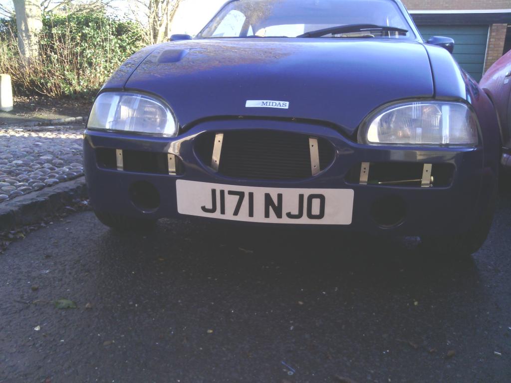 And careful positioning got their slats to line perfectly with the centre grill slats giving a more integrated look. While mentioning the side grills, I could see that they technically do nothing much to cool the rad just send road water and dirt directly at the coil and alternator which is less than ideal, 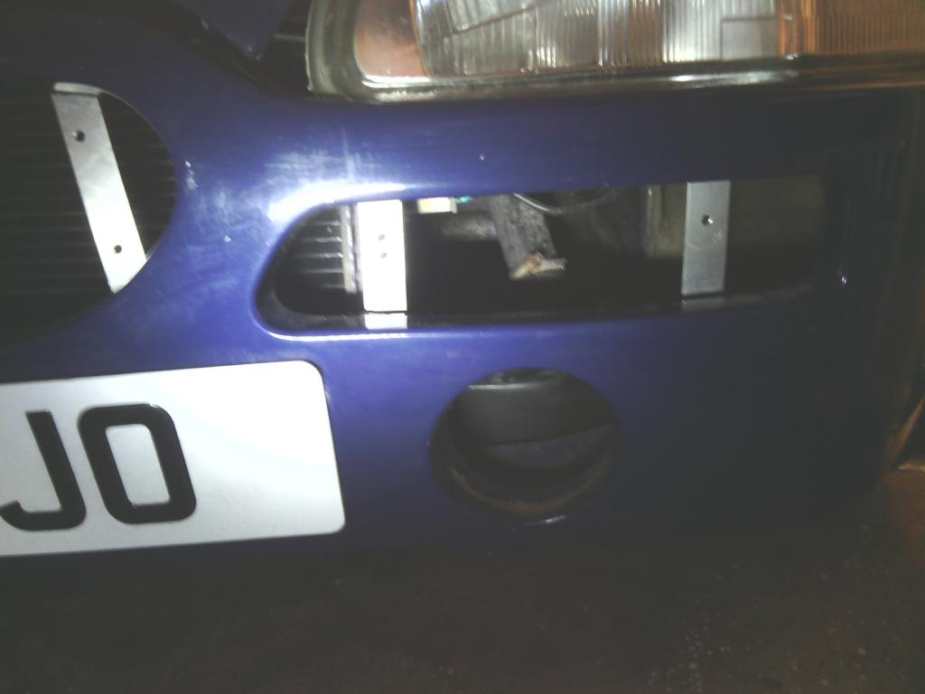 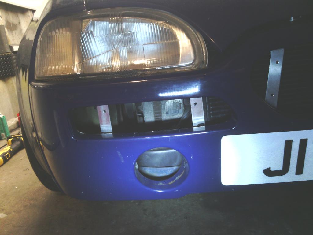 so using an offcut from my Quantum mud flaps I made I knocked up 2 blanking strips that once bonded to the rear of the ally angle brackets block off most of the opening just leaving a small opening in front of the only exposed portion of the rad, this may even increase airflow through the rad since the easier path for the air to take is now removed and should force air through, anyway no issues so far, 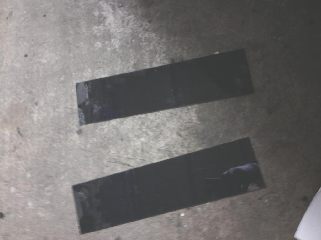 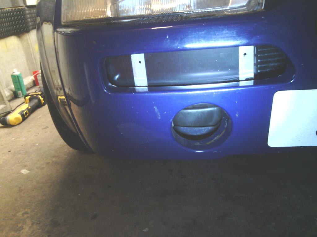 and the finished grills look spot on. 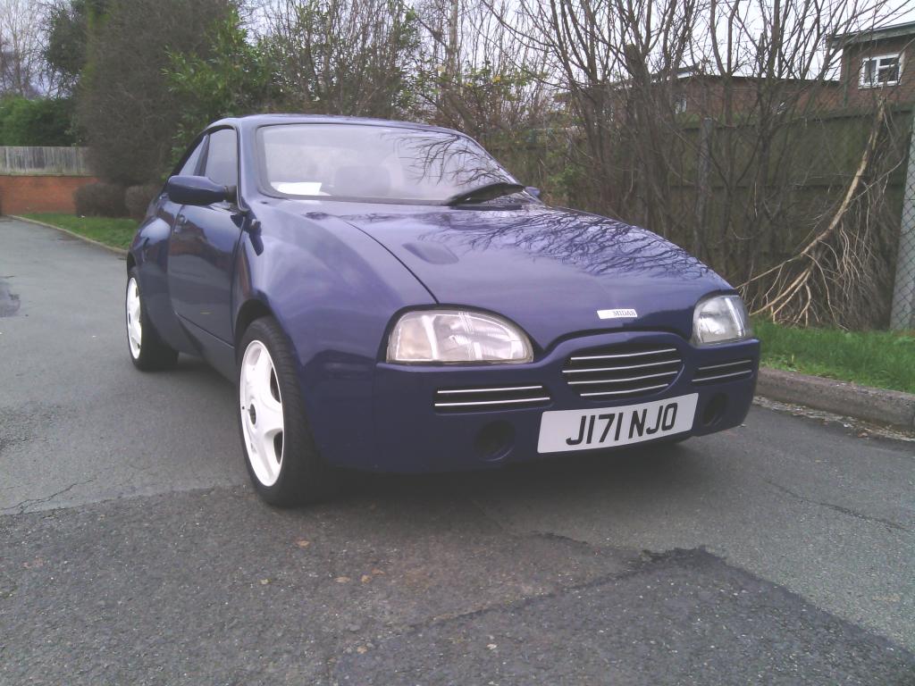 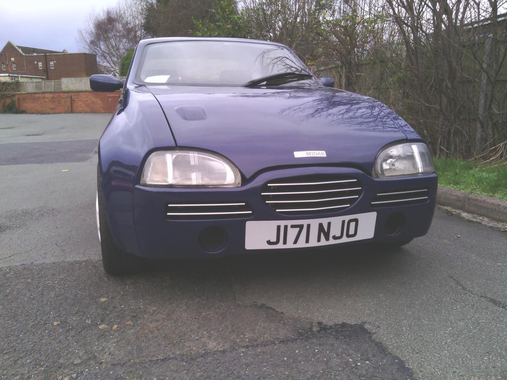 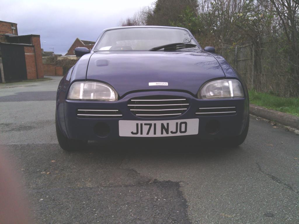 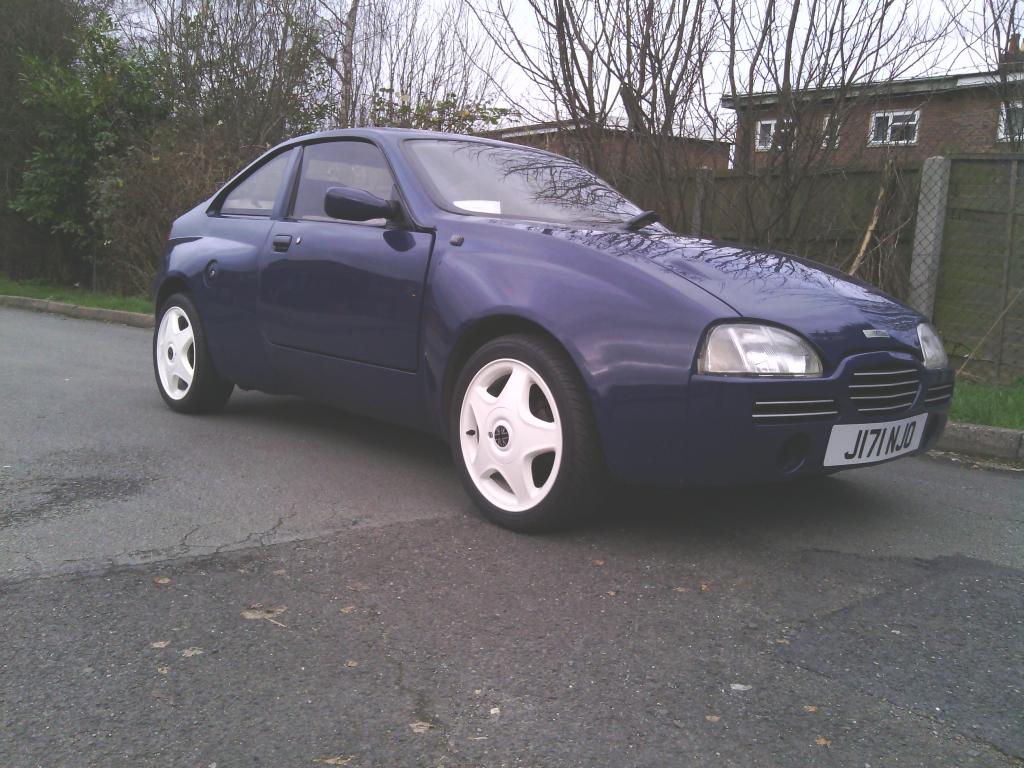 As for the angle at the front 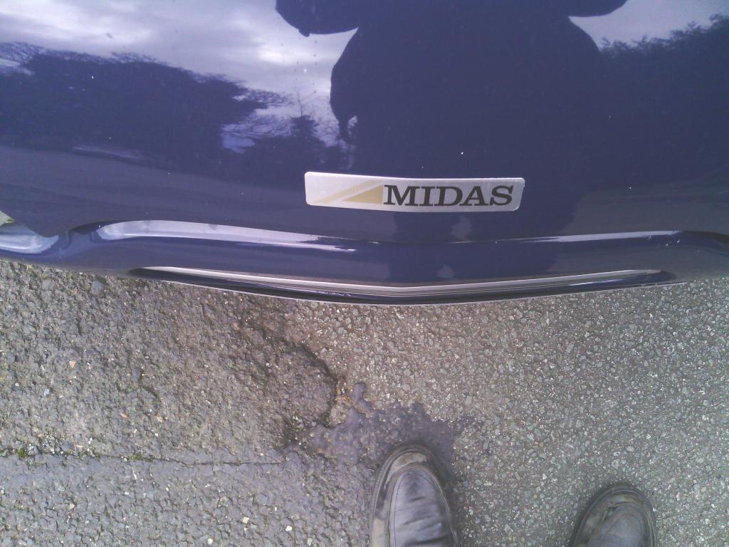 It was almost made for the job. | ||
| Jin |
| ||
| Regular Posts: 159    | JAN 2015 Some more jobs ticked off the list, the doors have been a total PITA To begin, I realised some time ago the driver’s side door glass sat noticeably lower at the top than the passenger side, more than just cosmetic it meant the seal didn’t seal due to the glass not touching it, a quick check with a rule saw the glass protrusion out of the door to be identical side to side thus ruling out a quick fix of just raising the door glass in the runner assuming that was the issue, the glass couldn’t go any higher anyway due to the front quarter piece where the mirror bolts to – time for a think. 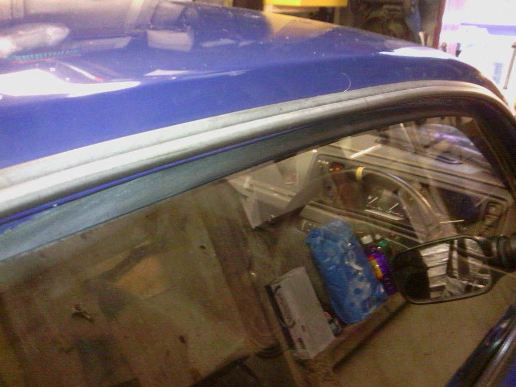 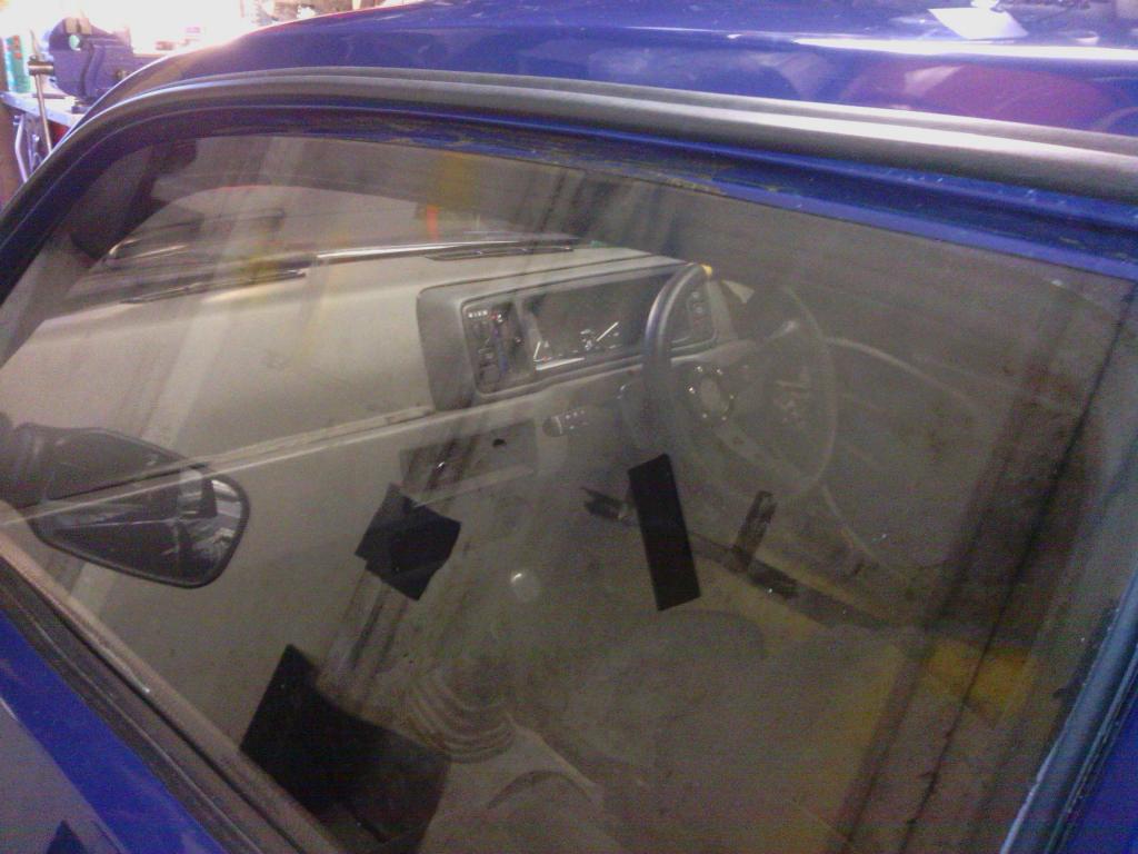 The problem would appear to be historical because old pictures of the car seem to show this issue also. After much head scratching and measuring in as many ways as I could I found that on my car (the prototype) the driver’s side door shell is about 7mm shorter in height than the passenger side, thankfully the frame opening is identical to within 1mm so just a localised issue to the door. Obviously this needed addressing, I couldn’t cut and section the door since the rear edge lined up with the rear quarter perfectly so the only real option was to raise the whole inner frame of the door by 7mm along with the glass, easy enough to work on the rear fixings, they just needed re-drilling but the fronts required a little more thought, the obvious one being the 7mm gap that would now sit at the base of the mirror quarter triangle, so I made up a 7mm alloy spacer, 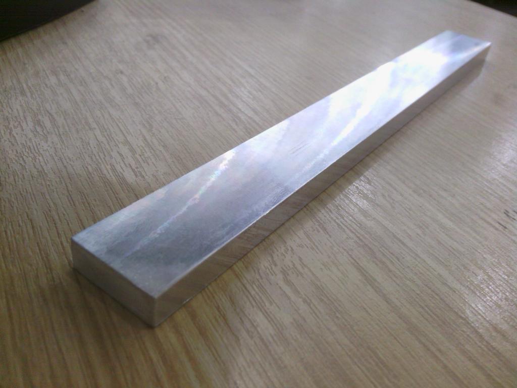 With that shaped and painted up 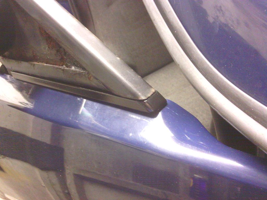 and the rear top mount trimmed down slightly where it now poked through the top of the door shell 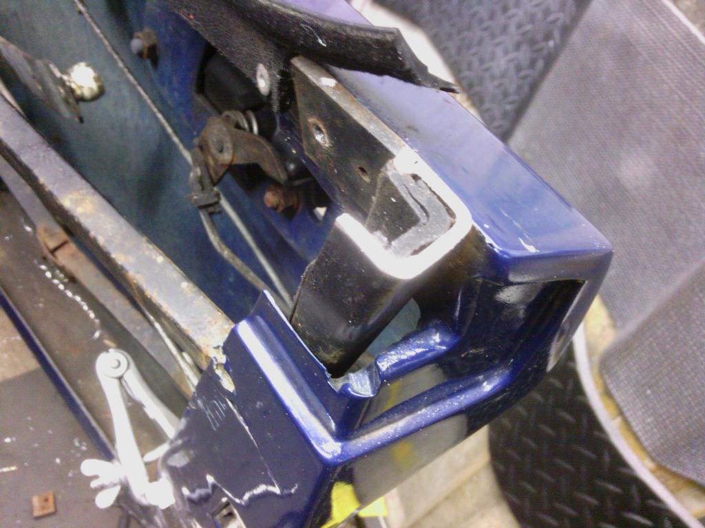 that was those taken care of, and brings us neatly to the next big problem with my doors – the panel gaps, the front upper and rear lower on both doors sat outside the body line by a minimum of 5mm giving a minimum twist on each door shell of 10mm across the length!!! 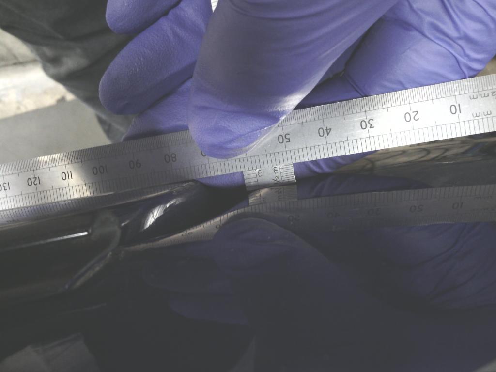 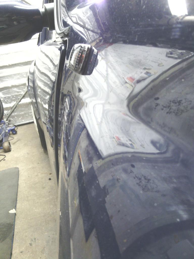 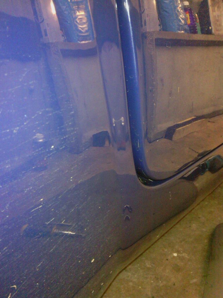 From what I have ascertained; the done thing is to shim the frame to bring it in line, the problem is that my frame is so out of alignment shimming using the original frame points would not rectify my problem (I’ll explain more later) First job to find out why the frame / door have come out of sync since it left the factory, looking at old magazine pictures the doors were in line once The rear looks to be an issue of the striker being fitted too high up in the door jamb resulting in more pressure being exerted by leverage at the base seal than the tiny amount at the top of the door shell, so a later job will be to re-locate the striker further down – best place would be exactly half way between top and bottom of the door shell The front alignment is governed solely by the hinges; adjustment fore and aft is catered for by elongating the holes in the A pillar to allow the hinge to move but there appears to be no practical way to adjust them in and out? With the door removed and some measurements taken it would appear that due to either weight over time or the door flapping about tin the wind (more likely since they have no check strap) the top hinge takes the brunt and flexes enough down its length to pull it out of line, taking a comparison between the (presumably interchangeable) top and bottom hinge off the door showed them to be about 5mm out of line with each other – just the right amount I needed to bring the door back to shape, so with the top hinge in the vice and gently persuaded back to its original shape with various instruments of torture I could then enjoy the task of replacing them onto the door and door to the car approx. 20 times (I’m not kidding) 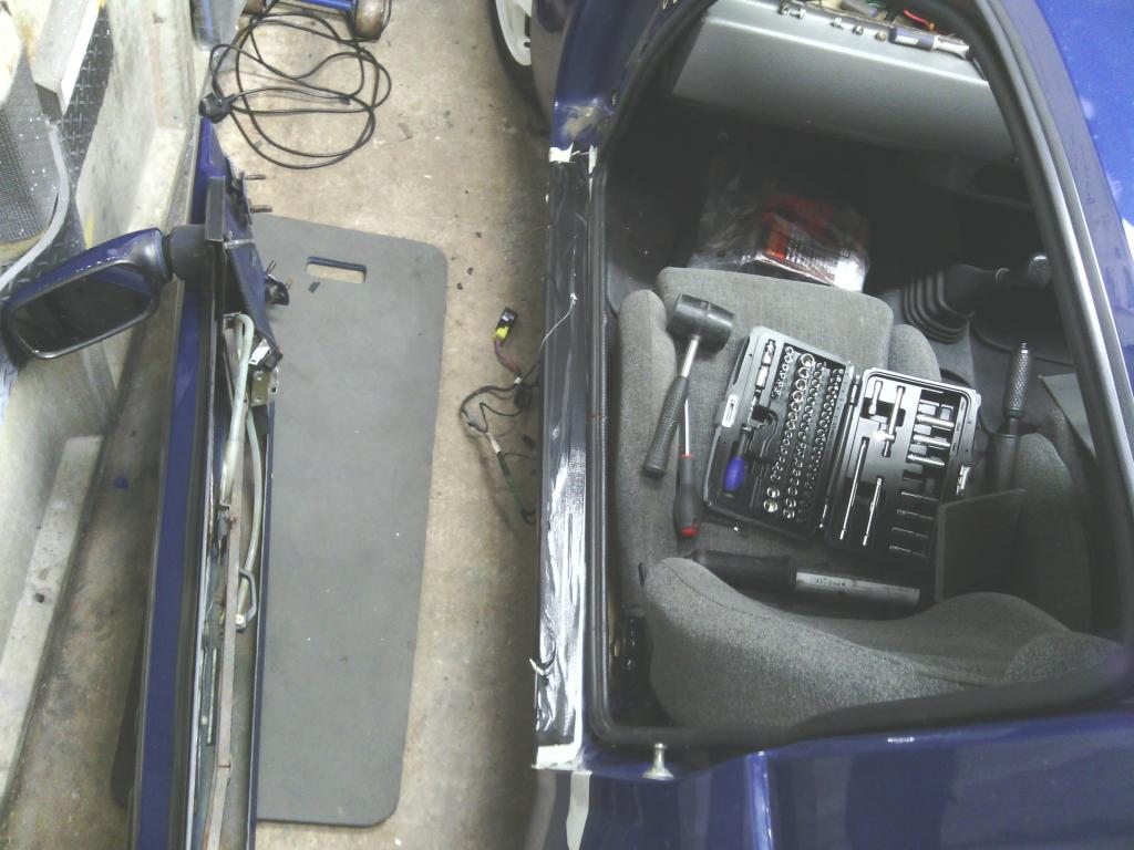 until finally the fit and finish was perfect. 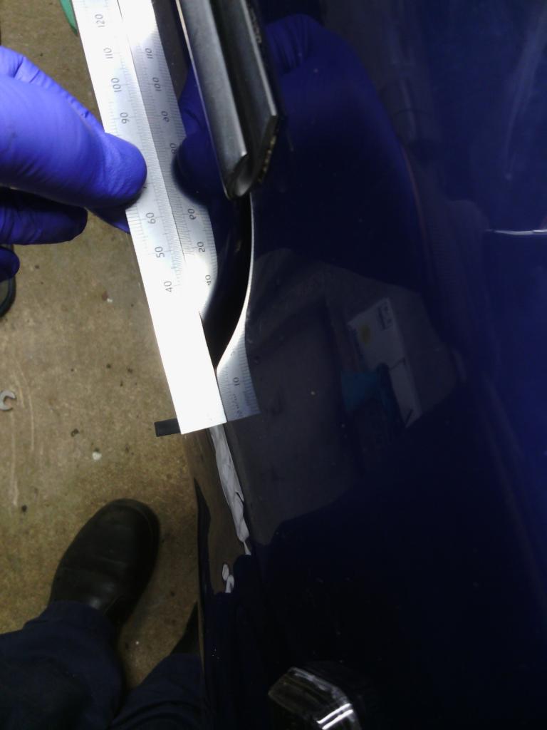 All the rusty hinge mounting bolts replaced with stainless steel. But what to do to prevent reoccurrence?, I’m sure I’m right as to why the hinges bend, the 3 bolts that hold the hinge to the door are in a straight line on the door albeit at an angle and the pivot is a fair distance away from them so any flexing of the door even gently; results in the hinges flexing and ultimately bending over time –you can confirm this by opening the door and placing a fingertip in the small gap between the door shell and hinge pivot, then open the door gently to its stop, even the slightest gentle push causes perceptible flex in the hinge. The solution was to remove the doors (again) and drill though the back of the hinge close enough to the pivot but not so close as to drill into the tapered down section resulting loss of strength, then drill through the into the door shell from the hinge then remove hinge and enlarge the hole in the door shell to 5.5mm, the 4mm hole drilled into the hinge was tapped M5, 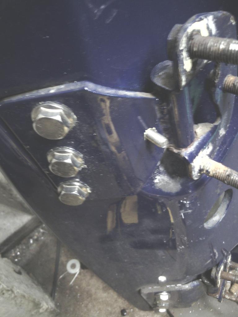 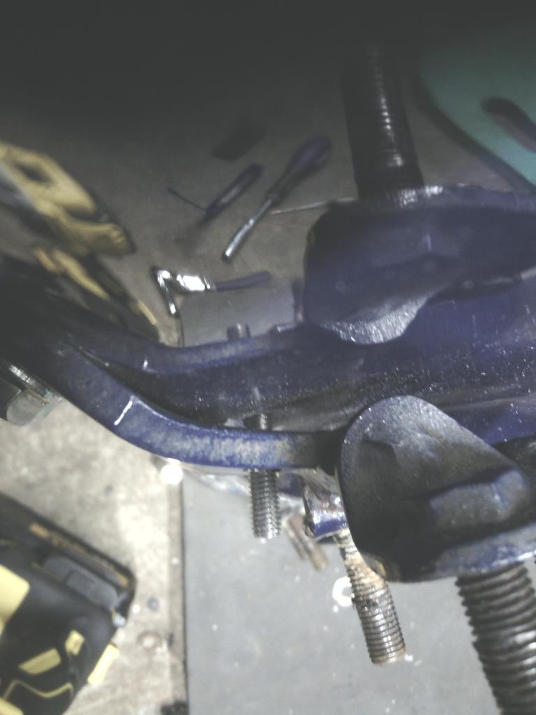 I chose stainless bolts because they would need cutting down to fit 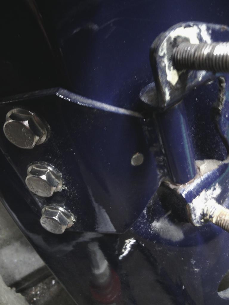 and I chose CSK heads because the inside of the door shell and hinge arm are not parallel, so using an M8 stainless washer over the M5 csk head allows a nice bevel to allow the head to sit at an angle but still grip all way round its head. 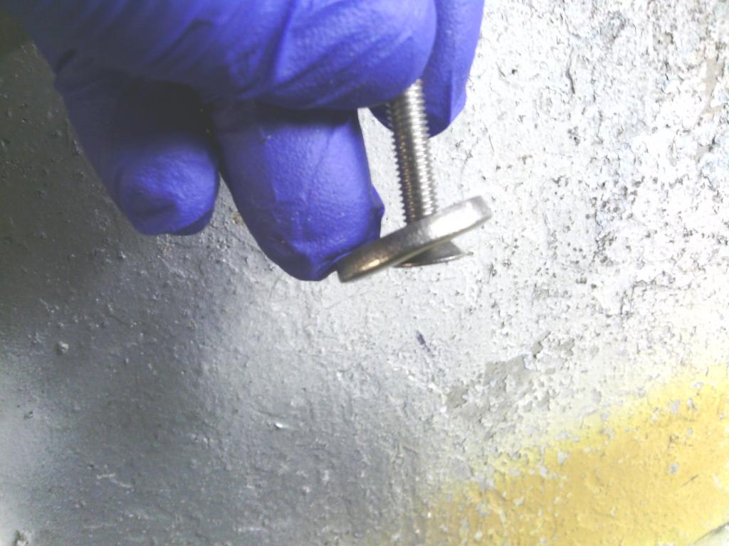 With that passed through from inside with a dab of Loctite to prevent rust in the cut thread of the hinge and nipped up inside the door, the bolt is enough to prevent any flex whatsoever, the feel is totally different when opening, rather than springing back closed they open to a firm satisfying stop, and as a bonus if you adjust the door hinges off the car to bring the outside of the door to a few mm from the outside of the car body the excess can be removed precisely by nipping up the screw in the door to provide a system of fine adjustment, this is why my alignment went from this  To this  So the good news was the 5mm offset in alignment was totally removed from the front of the door, the bad news is its now transferred to the rear bottom edge putting that out by over 10mm now – arse. I could see that at some point somebody had “shimmed” the rear lower mount with what looked to be a liquorice allsort but the relatively small contact area had resulted in the fiberglass warping, maybe straightening this out would help bring the door back a bit? 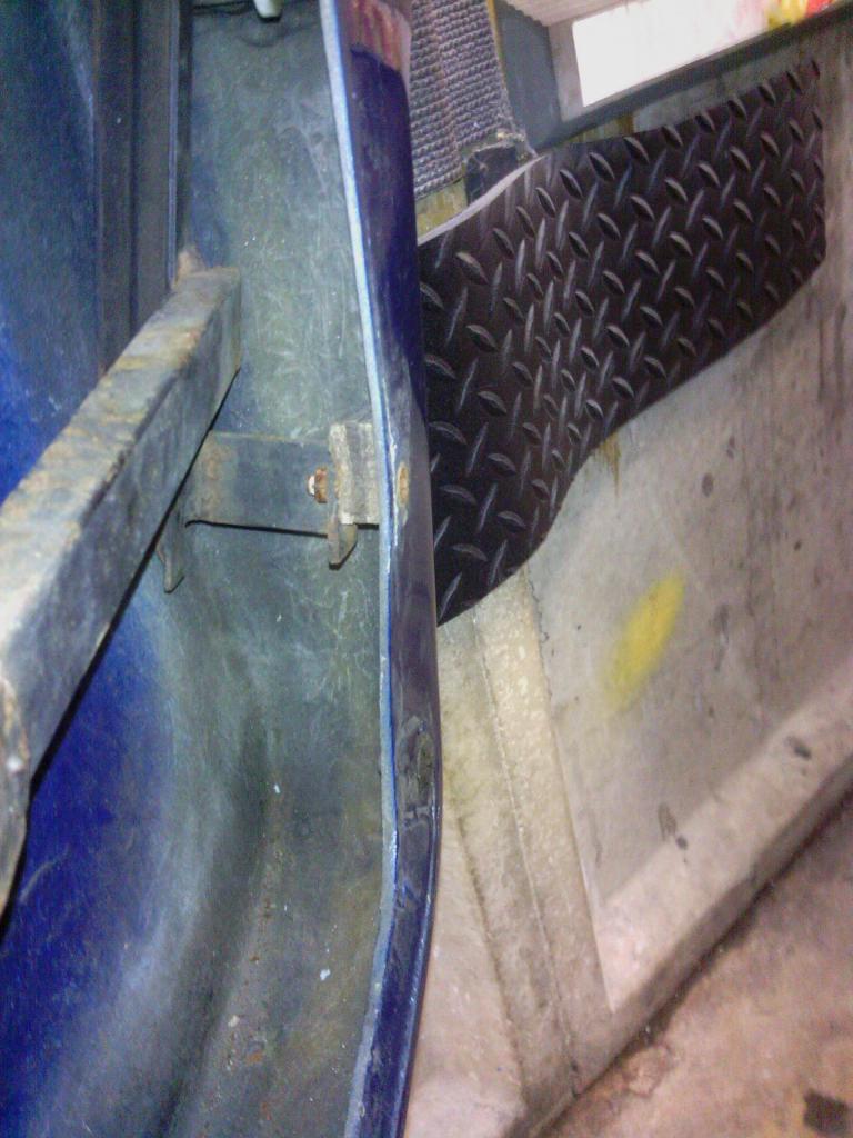 With the fixing removed the liquorice allsort turned out to be a chunk of plywood - oh well I ate it anyway, 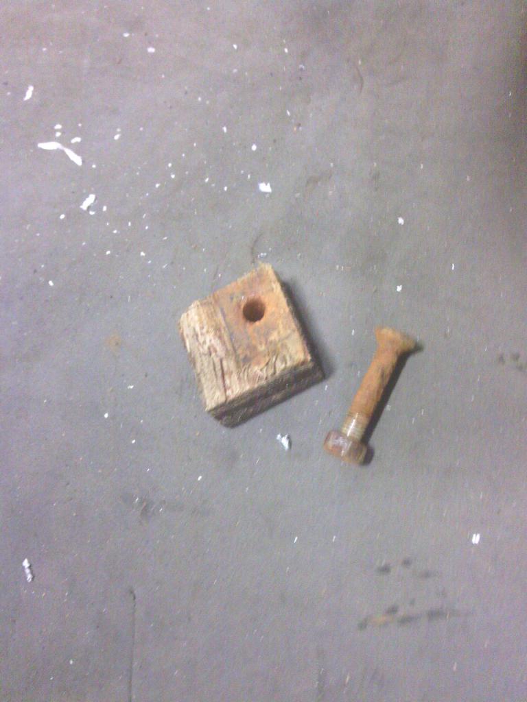 a new base for the bottom mount was made out of some 10mm thick aluminium 150mm long to help spread the load and straighten the fiberglass, also handy since it gave me a new option to mount the 7mm higher fixing point one on the driver’s door by tapping an M5 thread into the aluminium rather than drilling a through hole into the fibreglass door frame 7mm from the first hole which would weaken it for sure, so now both doors have secure rear frame mounts and hinges, and the straightening of the fiberglass door shell did help the rear lower alignment but not much, either way it is a vast imptovement 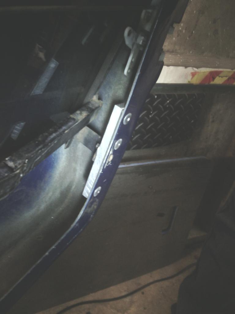 to address the issue the rear lower frame mount needed to move towards the inside of the outer door skin from within, but they were already touching, I managed to trim about 3mm off each so I should shim the mount with washers but still nowhere near enough, the front mounts can’t move away from the inner door skin (needed to pull the rear edge inwards – to be honnest i prefer the Quantum setup) because the lower mount would need to pass through the door shell return edge to do so and there was no obvious way to adjust this. feeling a bit desperate and since I had to rework the driver’s side anyway due to it being sat 7mm higher 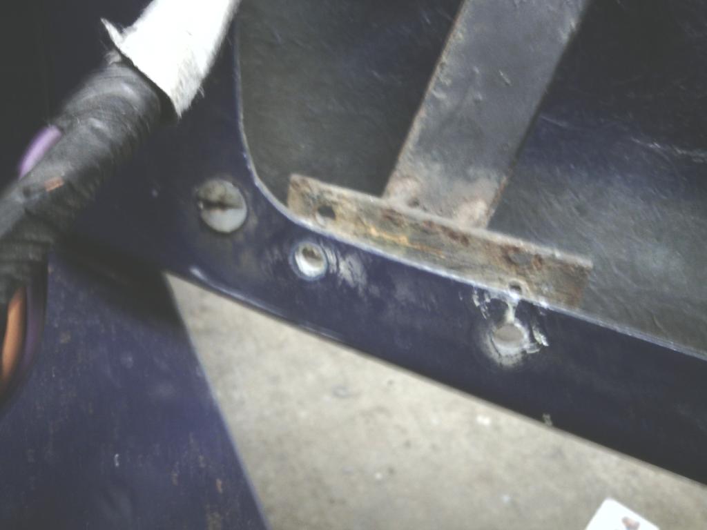 I took the decision to chop off both front lower mounts and start again they were in a right mess anyway. 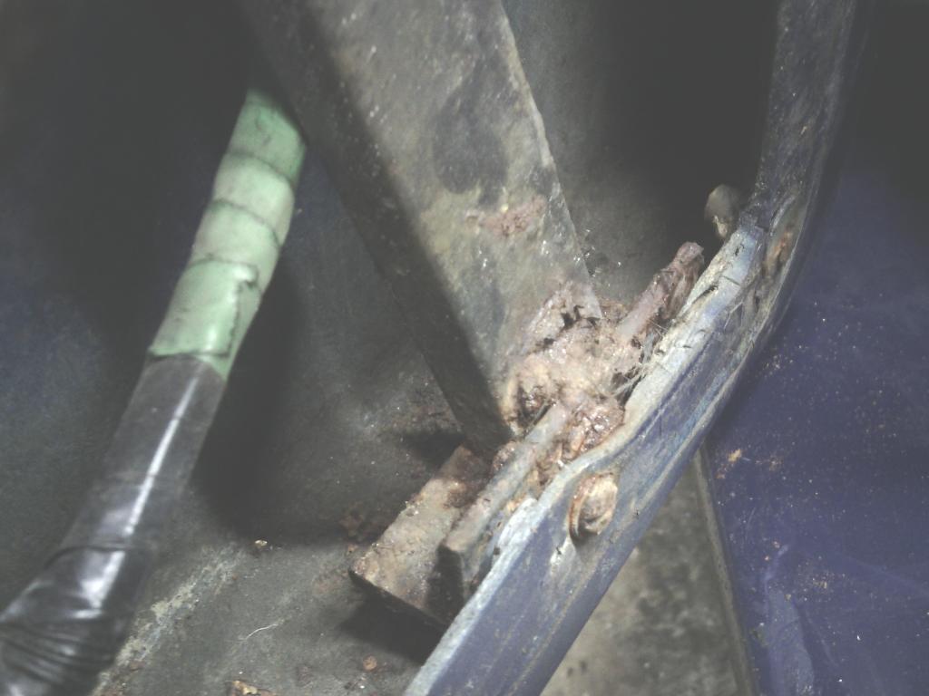 Working on the driver’s side, The first incarnation was to recycle the old bonnet buffer angle mounts and bolt them to the inner frame lower leg and then through the base of the door shell itself to provide a firm base to hold the frame secure, with the inside of the frame shimmed temporarily with Lego bricks 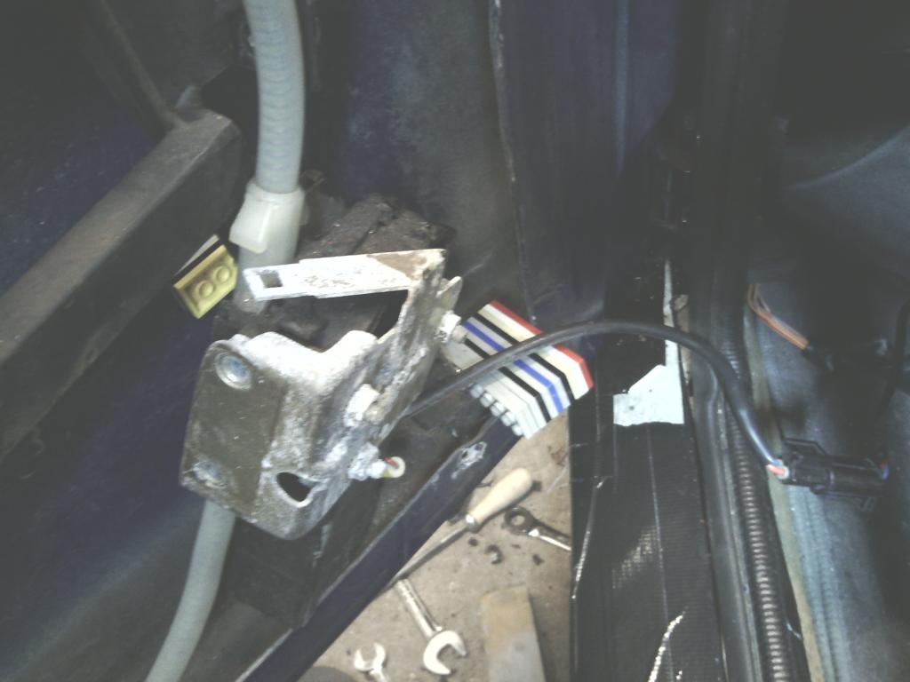 (don’t laugh, they are hard wearing and adaptable)I could adapt the angle bracket to fit that gap, I got some stainless button head bolts and turned the head down to fit in the door gap and set to it, it was pretty successful on the driver’s side allowing the lower frame mount to move inwards (to the interior) enough to pull the back edge of the door flush with the body line and not upset the alignment of the rest of the frame within the door- it’s not as strong as it looks unfortunately. 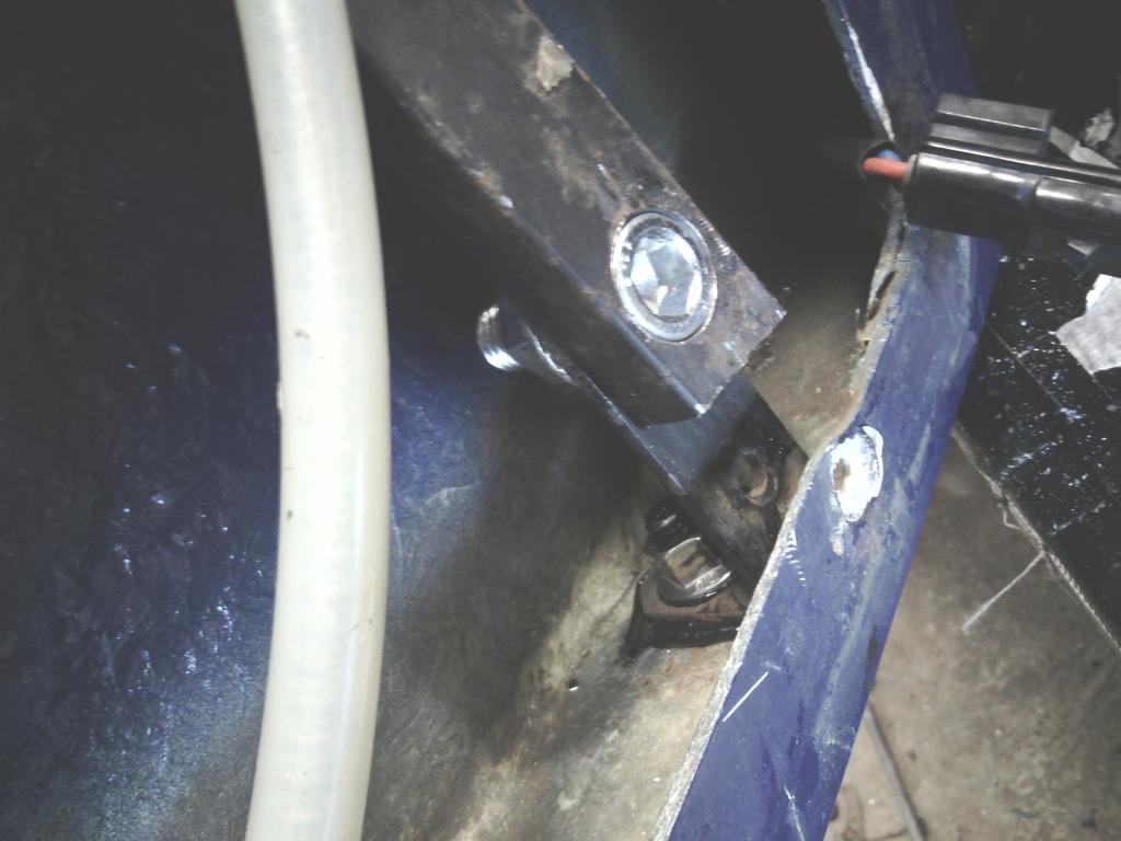 So with this done I moved to the passenger side, here things didn’t go so smoothly The passenger side had further issues in as much as the glass didn’t touch the seal by means of sticking out to the side of the car too much 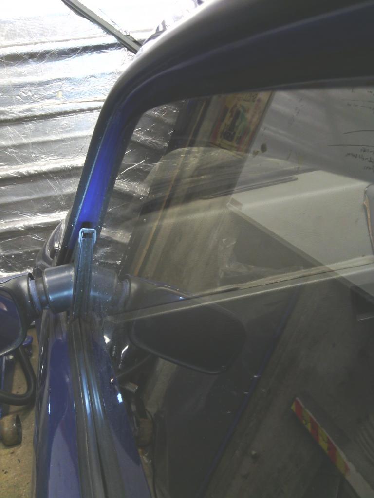 with the bottom leg cut down to match the drivers side, I started shimming the remainder of the front leg away from the inside of the outer door skin more and more and more until it became apparent this wasn’t going to work, to get the rear of the door flush to the body I had so much shimming at the front edge that the frame became distorted, the glass wouldn’t slide up and down the runners and the front quarter triangle where the mirror fits was pushed out away from the door seal to totally the wrong position, it never left the factory like this but here I am unable to attain the panel fit the car once had, so feeling a bit pi$$ed off and desperate (and daft to be honest) I grabbed the back edge of the door and twisted it between my hands trying to force something into shape, along with making some worrying creaking noises I also noticed a couple of things, 1. the door twisted very easily with just 3 points of the frame mounted, 2. As the door was twisted in the direction required to achieve panel gap nirvana I noticed the frame lower leg didn’t move in and out like expected but instead it moved along the length of the door – only by around 15mm total but that catered for a large movement at the rear, more than enough, I don’t know why this should be, I’m sure there is some mathematical equation to explain it but I didn’t really care, I had a plan. With the lower leg now chocked forcing it back down the length of the door , and after bit of trial and error I had the panel gap of my dreams and all other parameters correct – result  Problem now was the force on the front leg was quite considerable, not helped by its length and not helped by the bottom fixing of it now having a potential pivot on it due to my first mounting modification, so a plan B was required Since the requirement is to (relative to the inside of the outer door skin) pull the front leg down the door and push it away toward the interior I figured a new bracket would suffice along with a shorter leg to prevent it bending, so with the leg totally cut off just leaving the steel glass runner (as per the rear fixing) 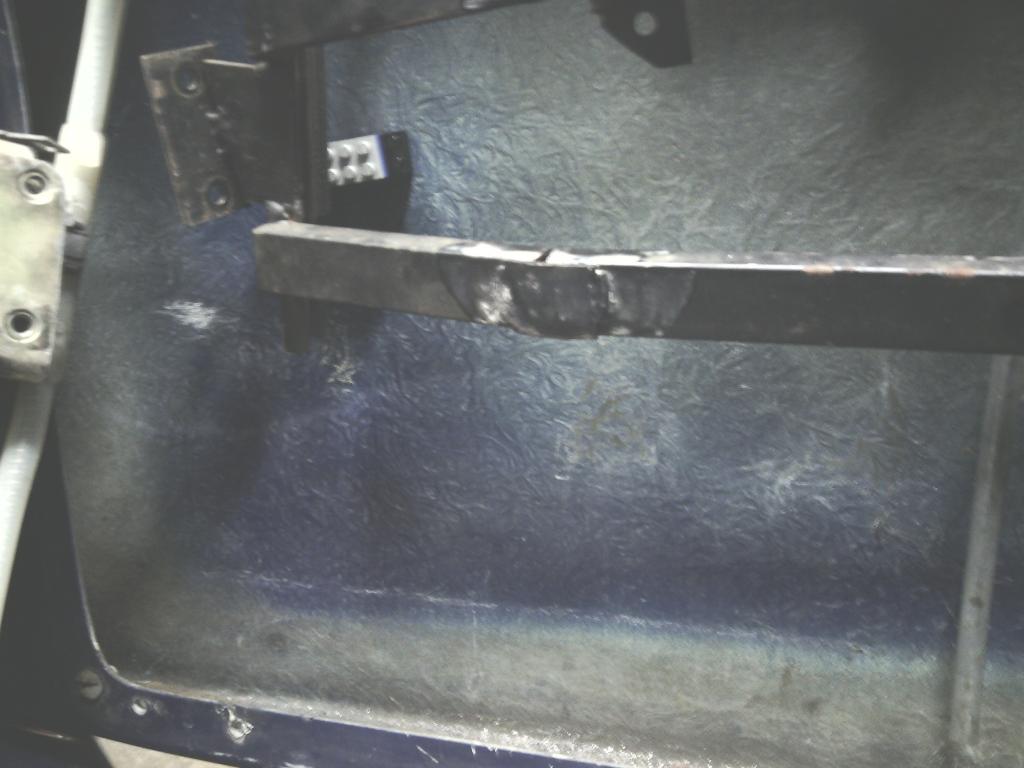 I made a plate from 10mm thick aluminium 300mm long x 50mm, more than enough to spread the load, this was then tapped M5 then had a 5mm thick angle bracket bolted to it, 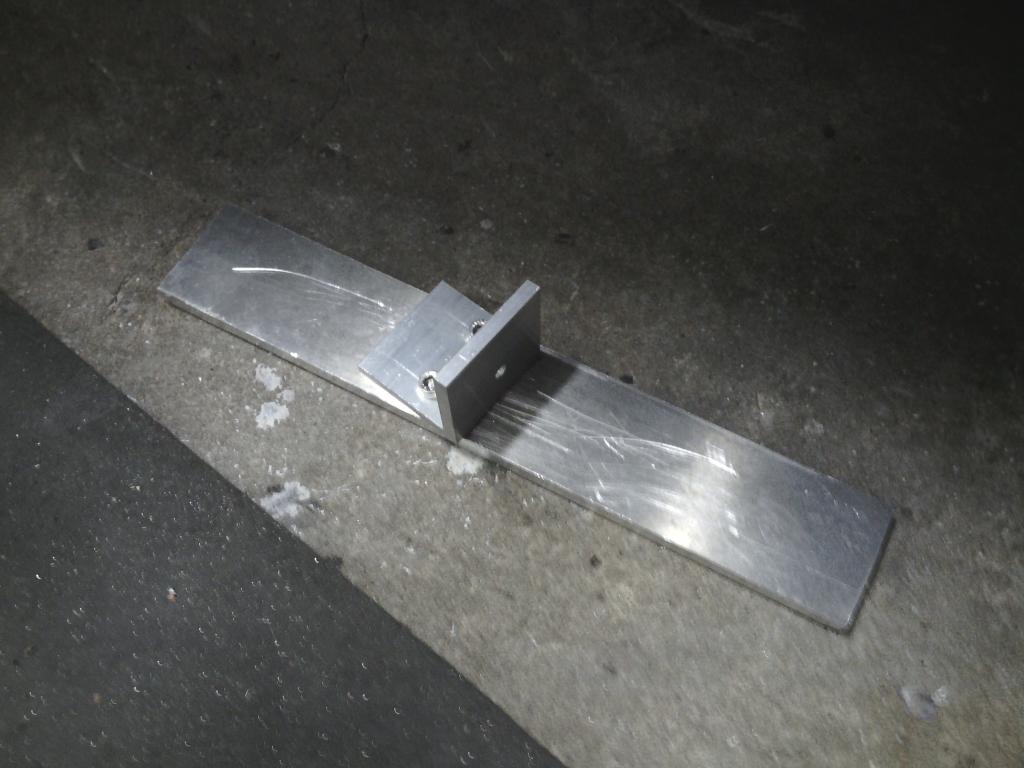 the plan being I can shim the steel glass runner relative to the angle bracket to push it further towards the rear of the door and thus correcting the door twist, and I can shim between the angle and base plate bonded to te door skin to correct any alignment at the top where the mirror base triangle fits – I hope I’ve explained that right All bonded into position and once set, the frame is rock solid on the door and the door shows no tendency to twist or bend in any way 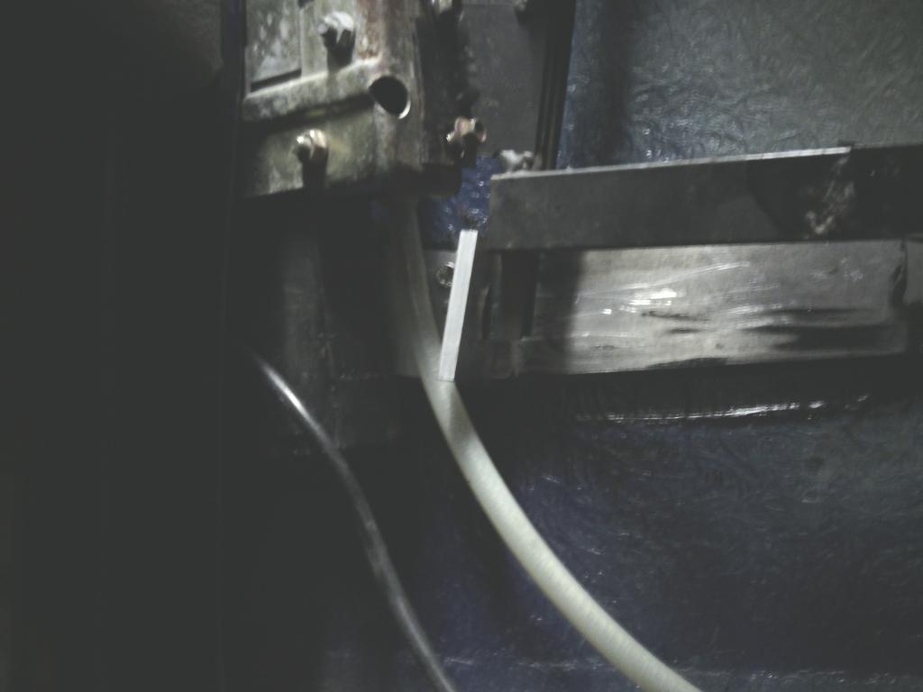 The passenger side frame was also removed and re-sealed where it met the door just to keep things even, so after all that my doors are perfectly in line and stand very little chance of wandering out of line again – next job removing the old mirrors and making some new custom mirrors and tailor made mirror basses…. | ||
| Jin |
| ||
| Regular Posts: 159    | FEB 2015 Since completing the door hinge mod and window frame adjustments http://midasownersclub.co.uk/forums/viewtopic.php?f=14&t=2178&start=50 I needed to do something about the mirrors, the base they mounted onto was in poor shape and there was now an odd looking spacer on the driver’s side to correct he door miss-match that needed hiding. I opted to remedy the situation by making some custom mirror mounts as I did with the quantum but rather than use aftermarket units such as the vitaloni I used before I wanted to try to utilise some OE ones for better quality, I always like the rover 25 / 45 /75 / lotus / Noble M12 units and they seemed to fit the bill for the Midas perfectly since if rover had continued production of the 100 for any longer they would have ended up on those and be branded a “facelift model” so off I went to find some 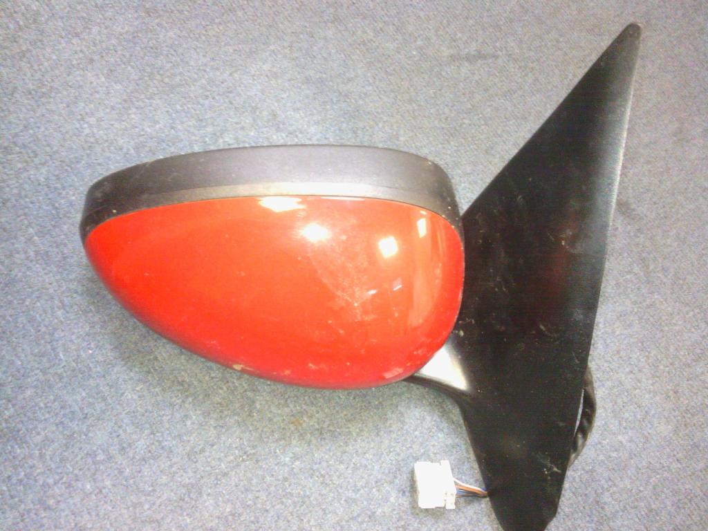 Stripped down 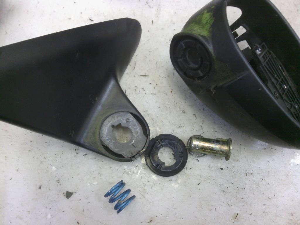 I chose electric because the glass clicks into place by pushing the glass and they only really need adjusting once, I didn’t fancy trying to feed wires through my housing and the manual adjustment ones flap all over the place with the control rods removed. I started by cutting x2 10mm thick aluminium bases, the mirrors will bolt through these, 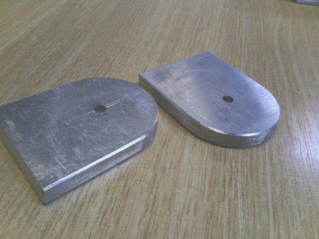 with the end face bevelled to put them at the correct angle for the door incline I drilled and tapped the end face to provide a temporary fastening prior to welding, I made some pointed screws to mark out the holes to be drilled into the triangle plate relative to the 10mm thick base 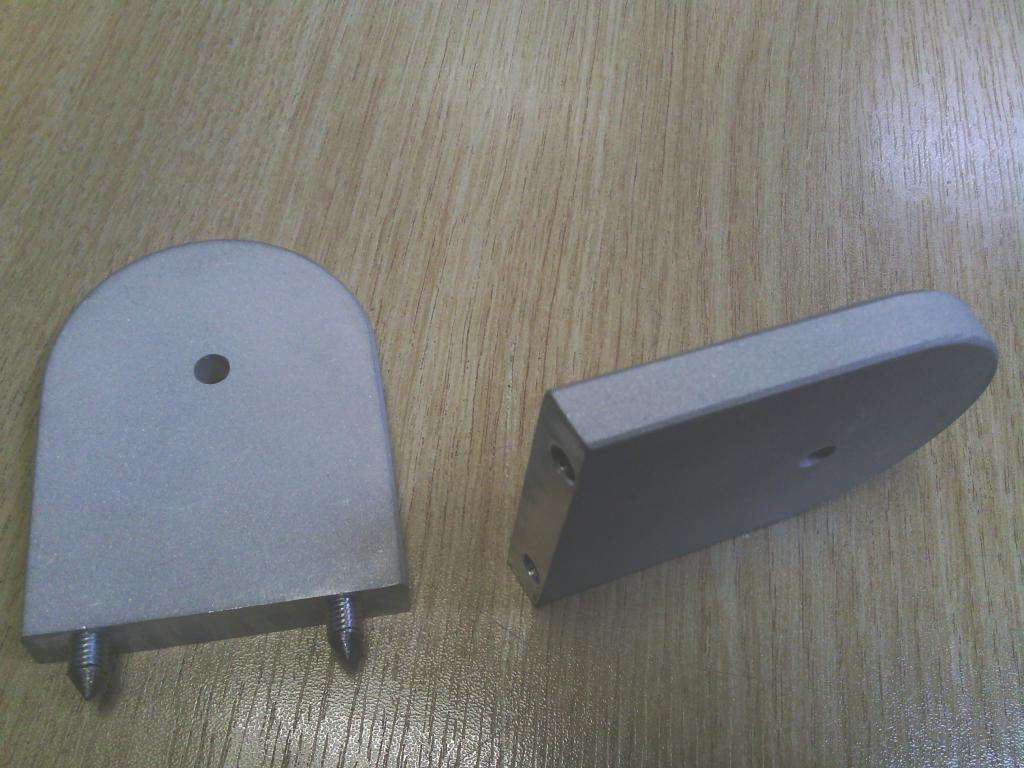 Cut out 2 triangles, one slightly larger to account for the door spacer 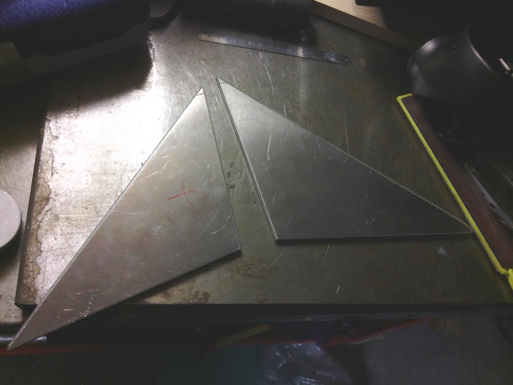 Drilled and bolted and then welded into place 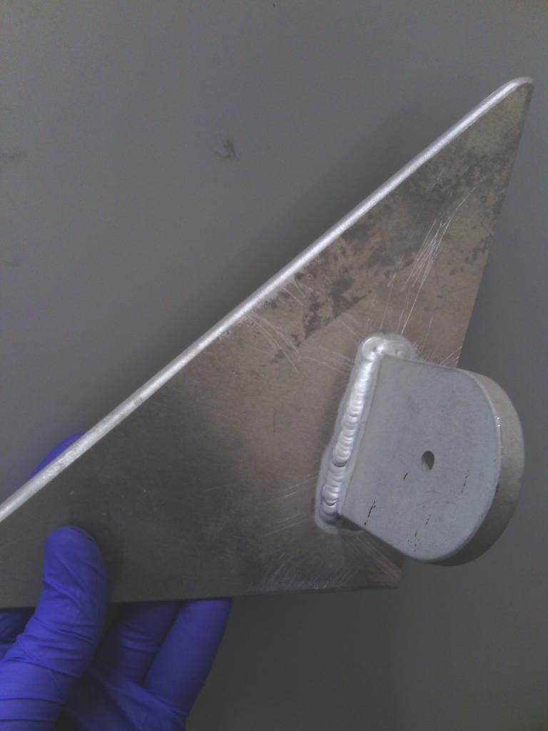 I also put an M10 aluminium stud on the rear to line up with the original hole in the door frame triangle to give extra support 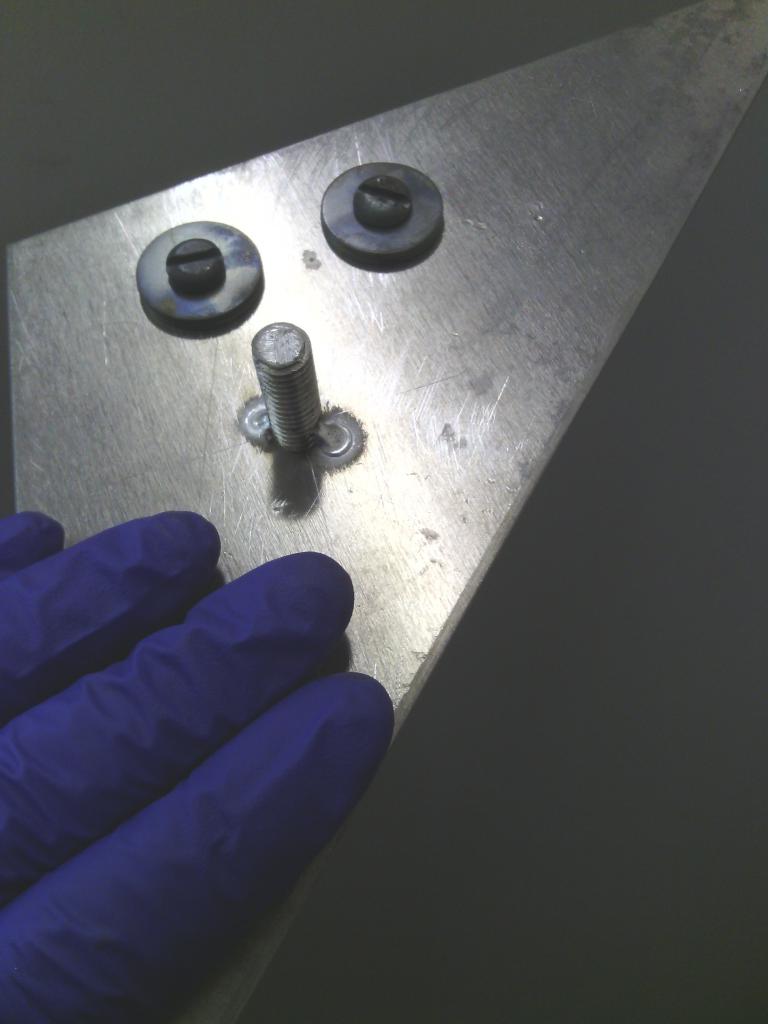 With that done it was time for a quick grit blast and a touch of filler 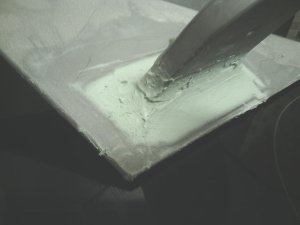 Smoothed 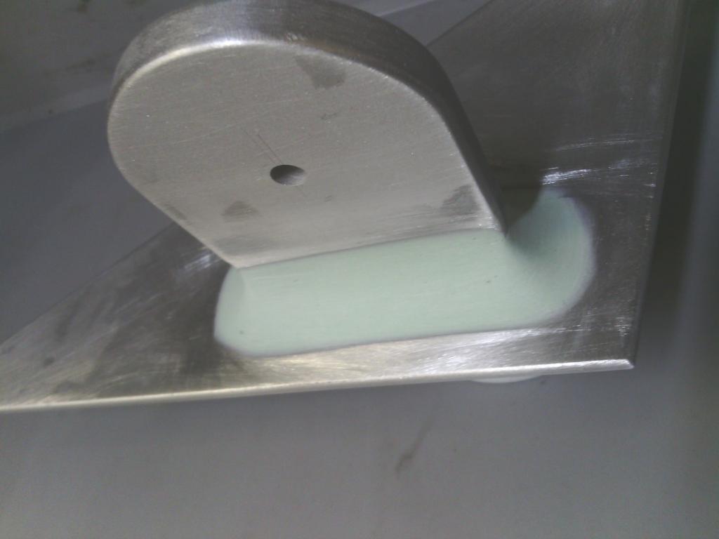 2k primed and guide coat applied, once smoothed down time for a topcoat of 2k pure black tint, the finish didn’t come out too bad 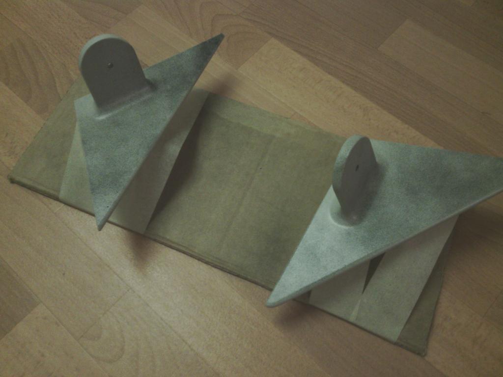 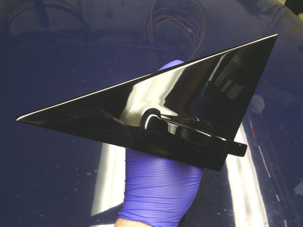 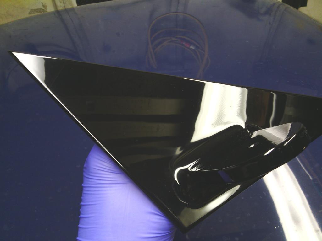 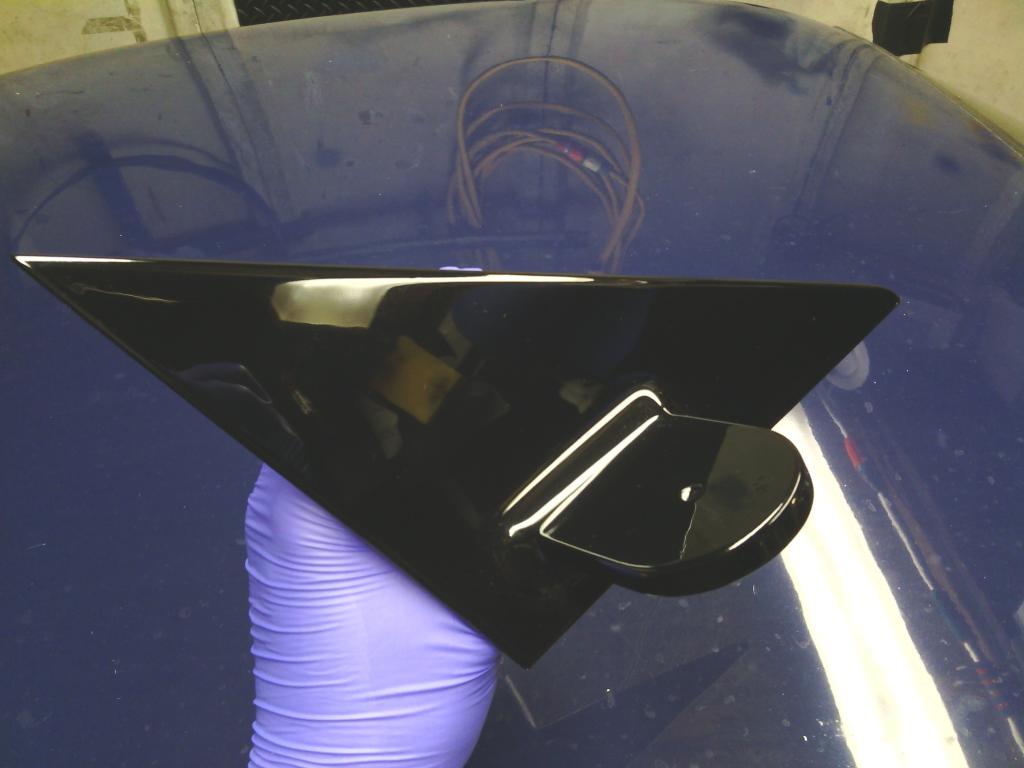 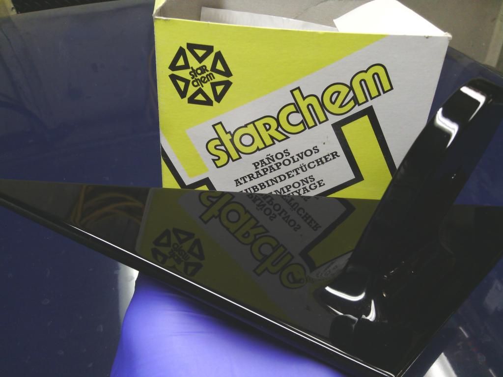 With that hardening off I set about restoring the door triangle frame, long term I will strip them both out the doors and probably powder coat after welding in new reinforcements but for now I really do need windows in the car on a daily basis so that will have to wait, the metal was in a bit of a state 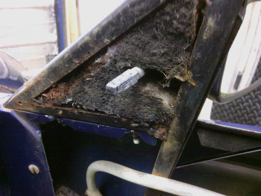 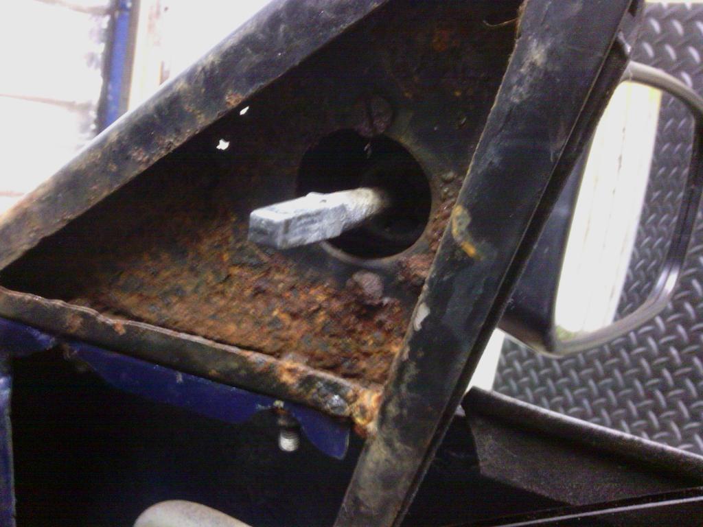 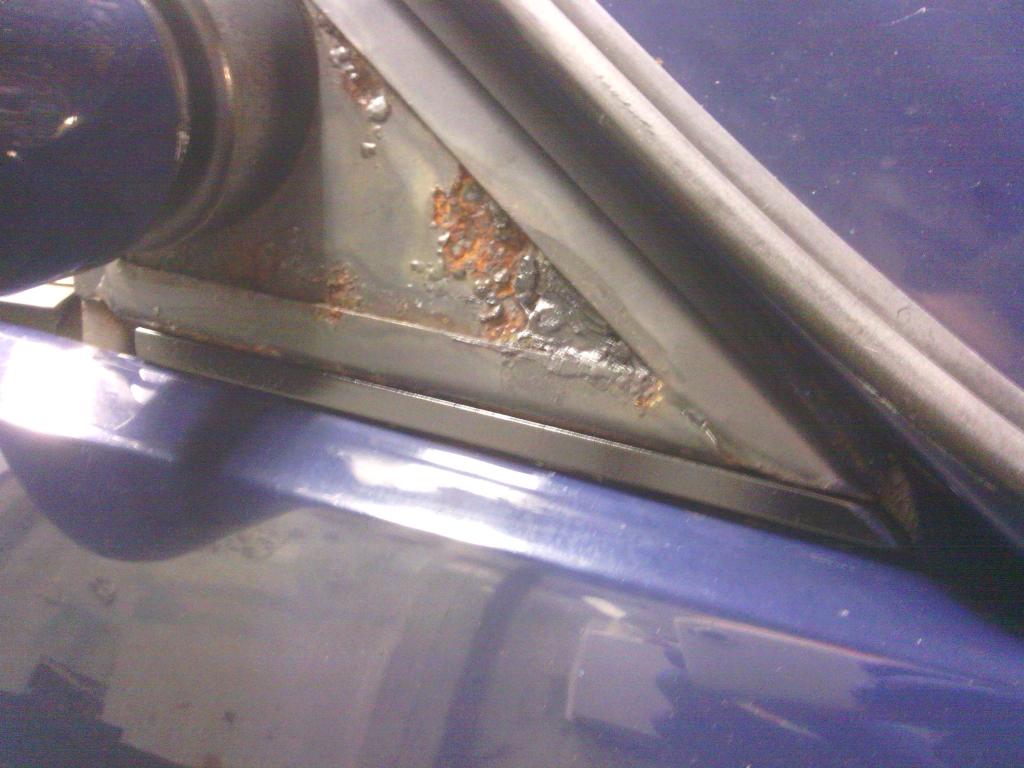 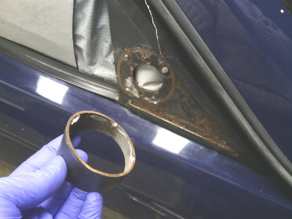 But I did grind the rust out and treat with Vactan which is supposed to be good 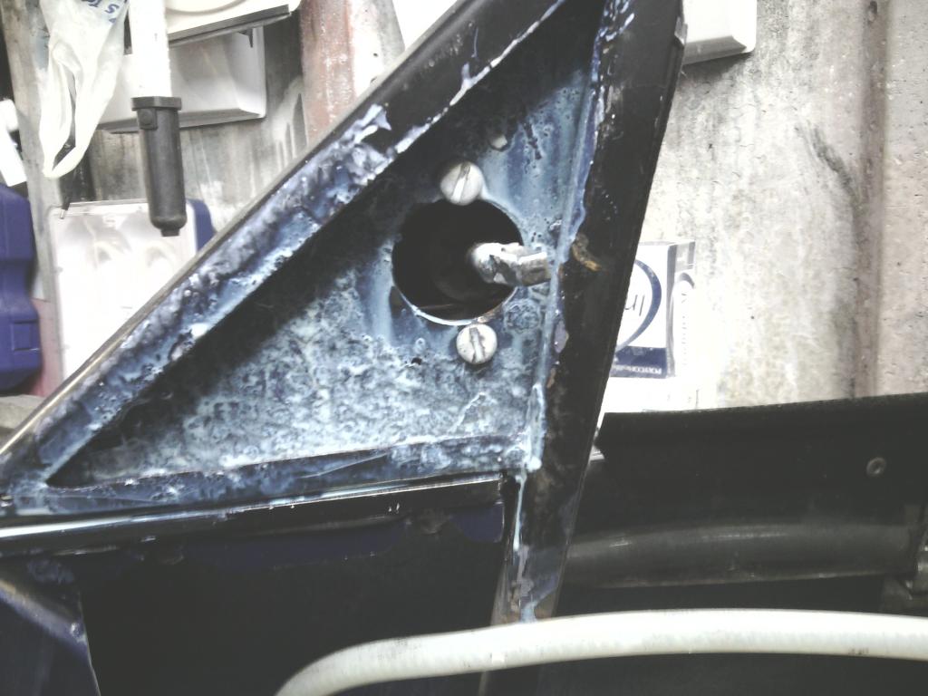 I also made 2 blanking caps to seal off the inside totally from water ingress, up until now water leaked in through this gap at the top and soaked into what I can only describe s mouldy donkey fur – no wonder the metal rusted away 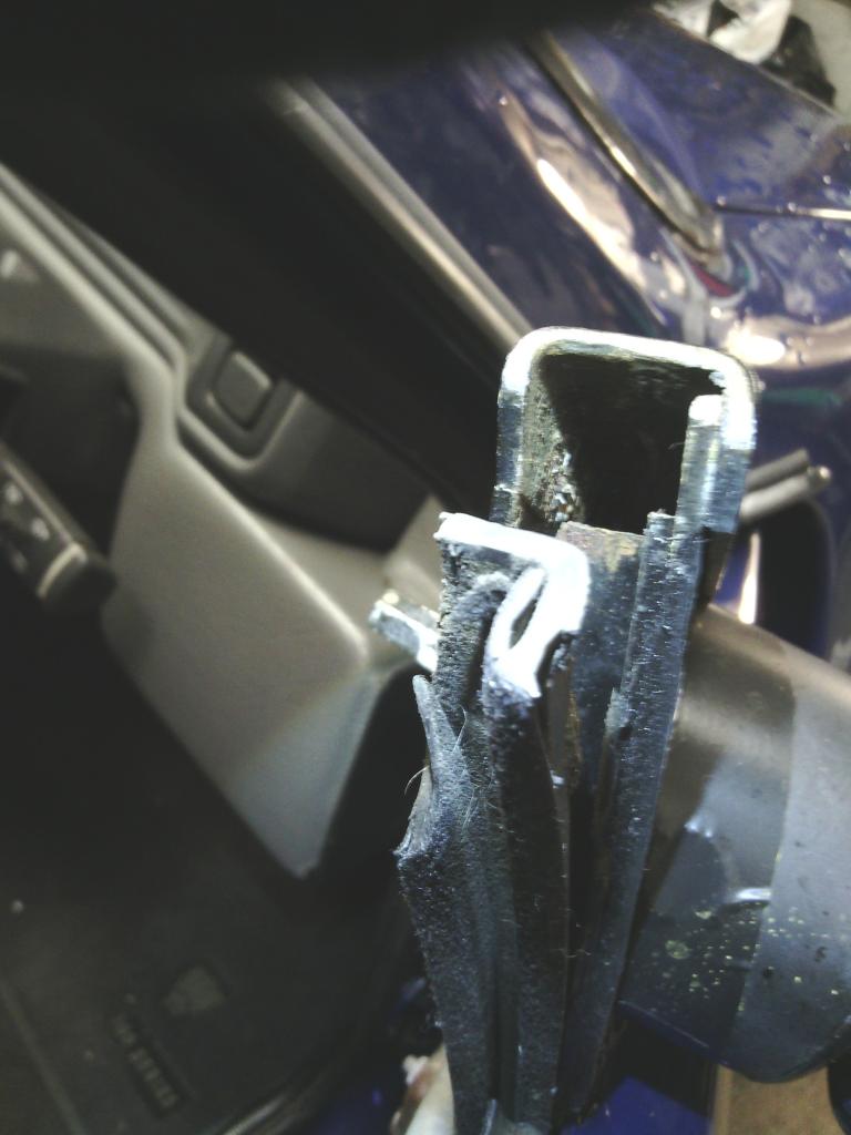 To remedy I made 2 plastic blanks from left over grill mounts and bonded them over the hole 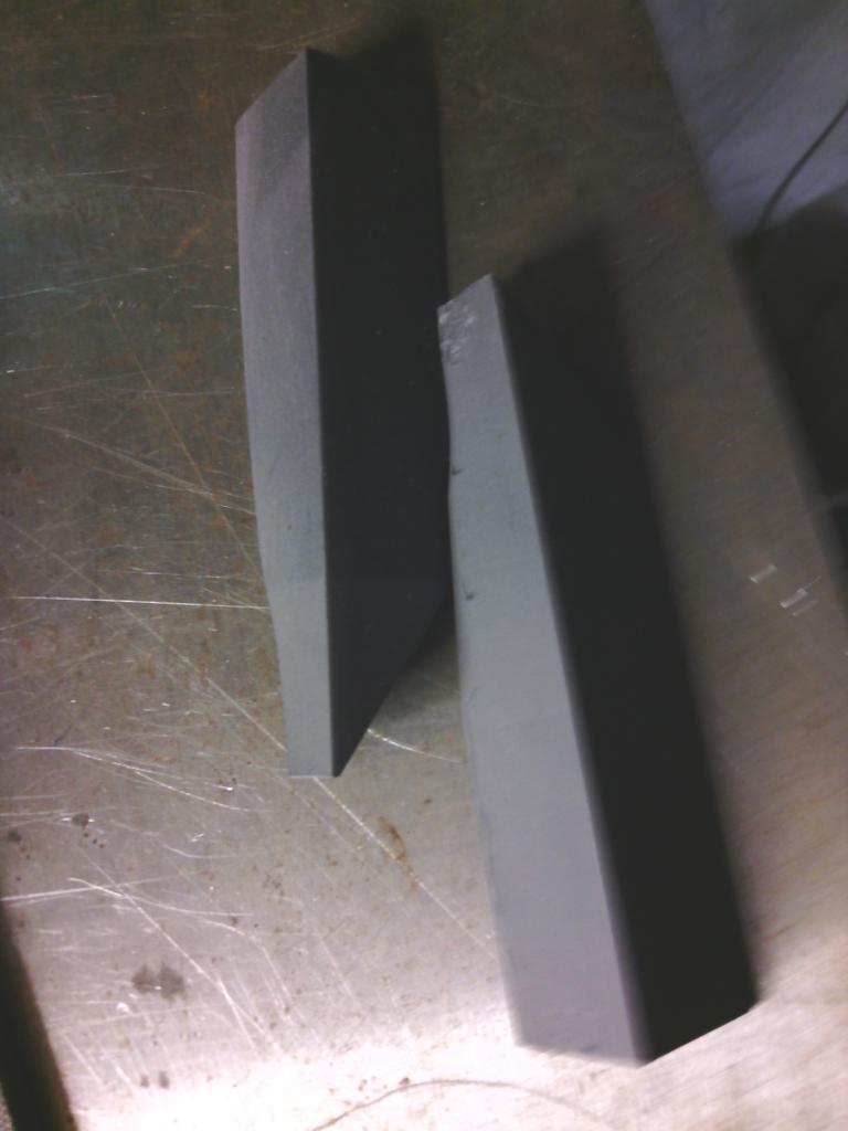 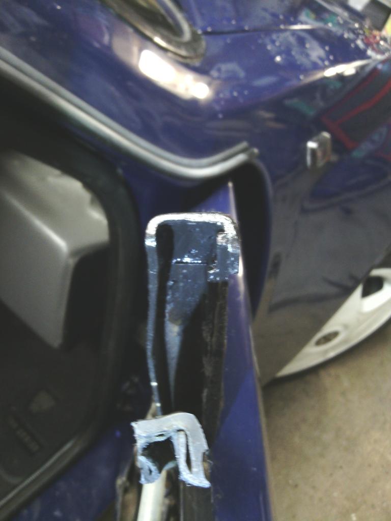 Should keep them dry for now, they will get welded once removed. back to the mirors, I normally bond things like this with polyurethane but this time I didn’t for 2 reasons, 1 I intend to remove them in the future to remedy the rust. 2 they may not bod as well due to said rust, so to be safe I used an acrylic based adhesive that although strong is nowhere near as impossible to remove as the polyurethane, even so I filled the whole void behind with it to totally seal out air and moisture, the M10 stud there as a safety precaution to keep them held secure, as it happens I doubt they are going anywhere in a hurry 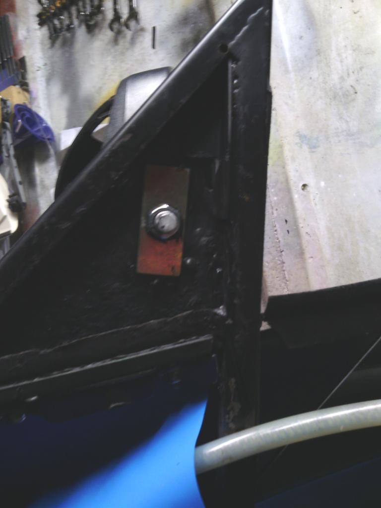 That now done I had to make a small ally spacer to locate in the mirror hole 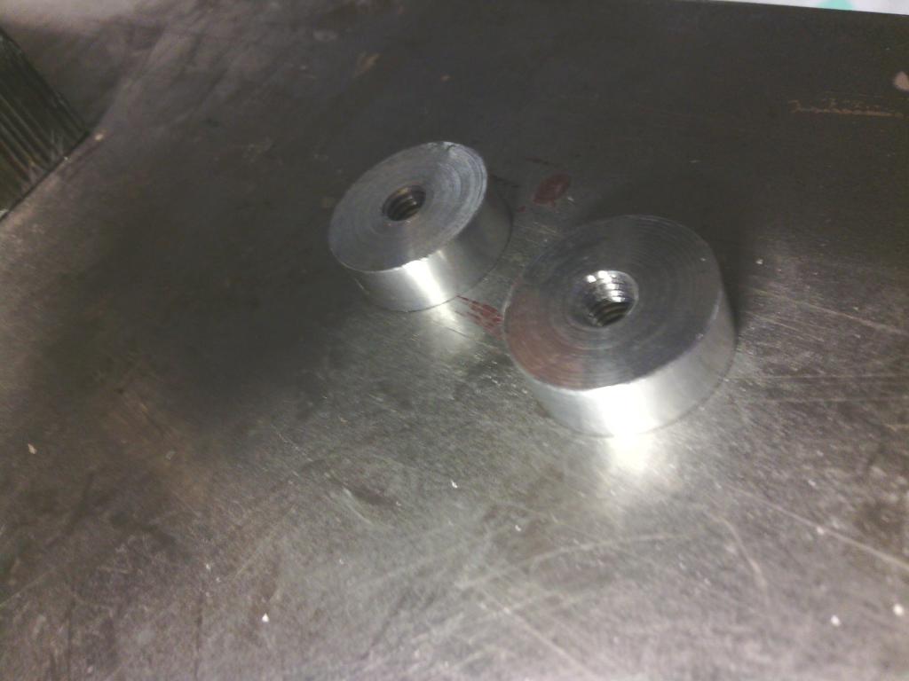 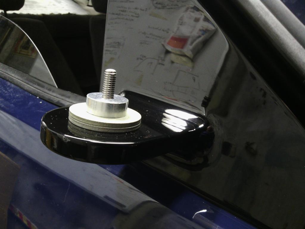 And support it on 2 ally washers to get the height right, the spacer is threaded and sits slightly lower than the mirror mount hole so with the top held down with a stainless washer and nut, the stiffness of movement can then be controlled but tightening or whatever. 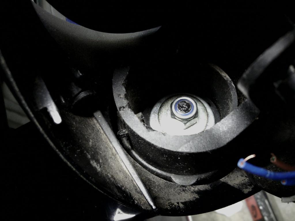 Although the mirrors look big (everything looks big next to this car) they actually stick out less than the standard units 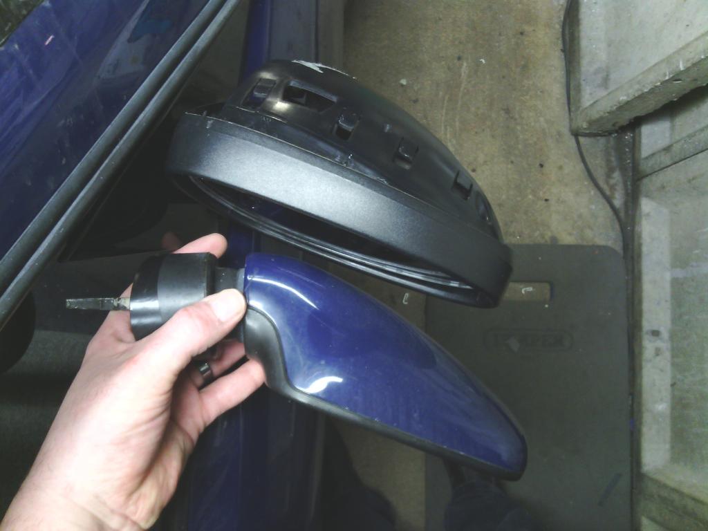 I then painted the mirror caps in RAL9010 to match my wheels 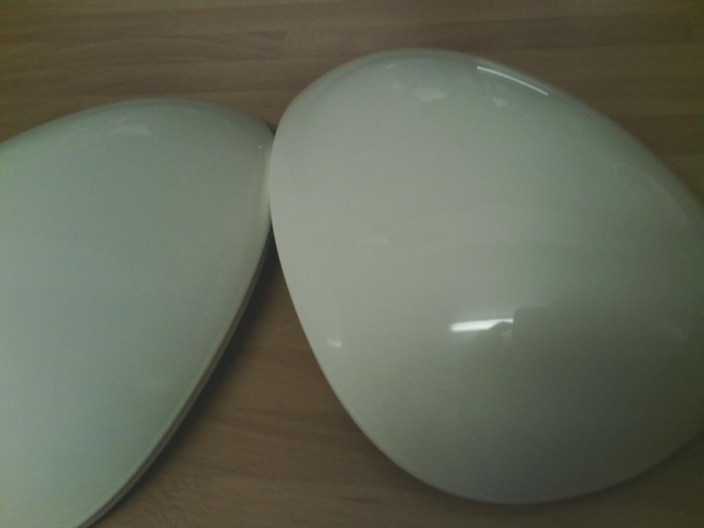 All fitted up and adjusted and away we go… please excuse sate of car, its used rain or shine every day 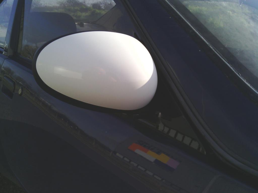 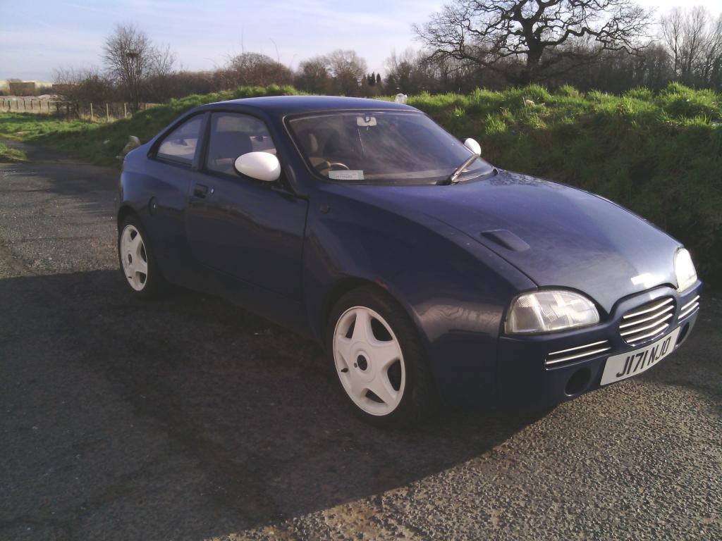 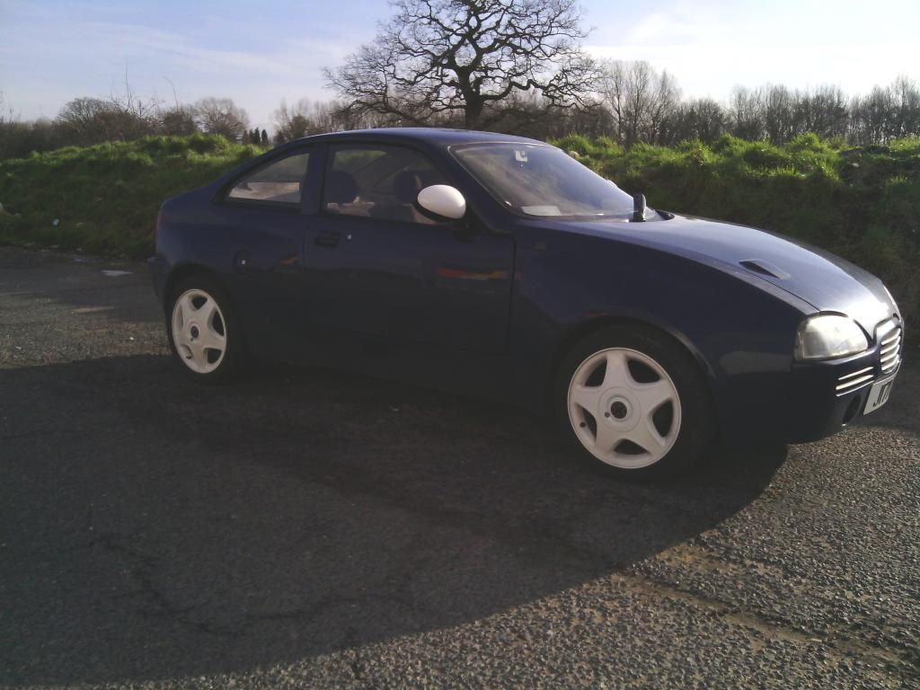 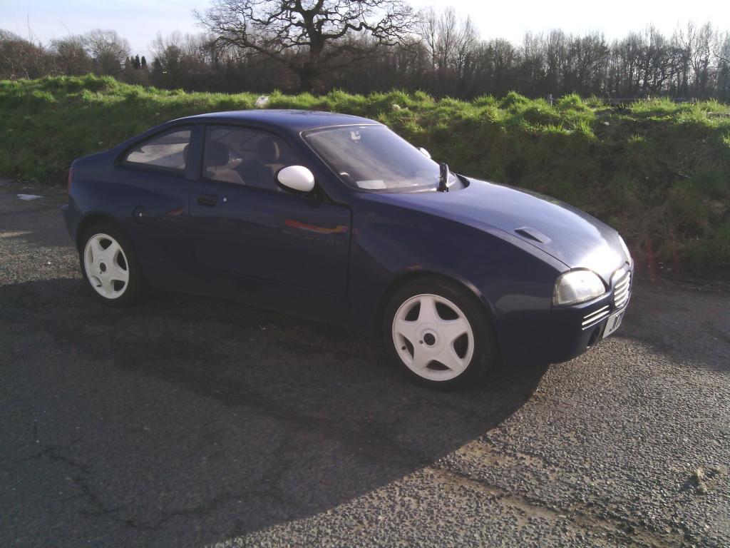 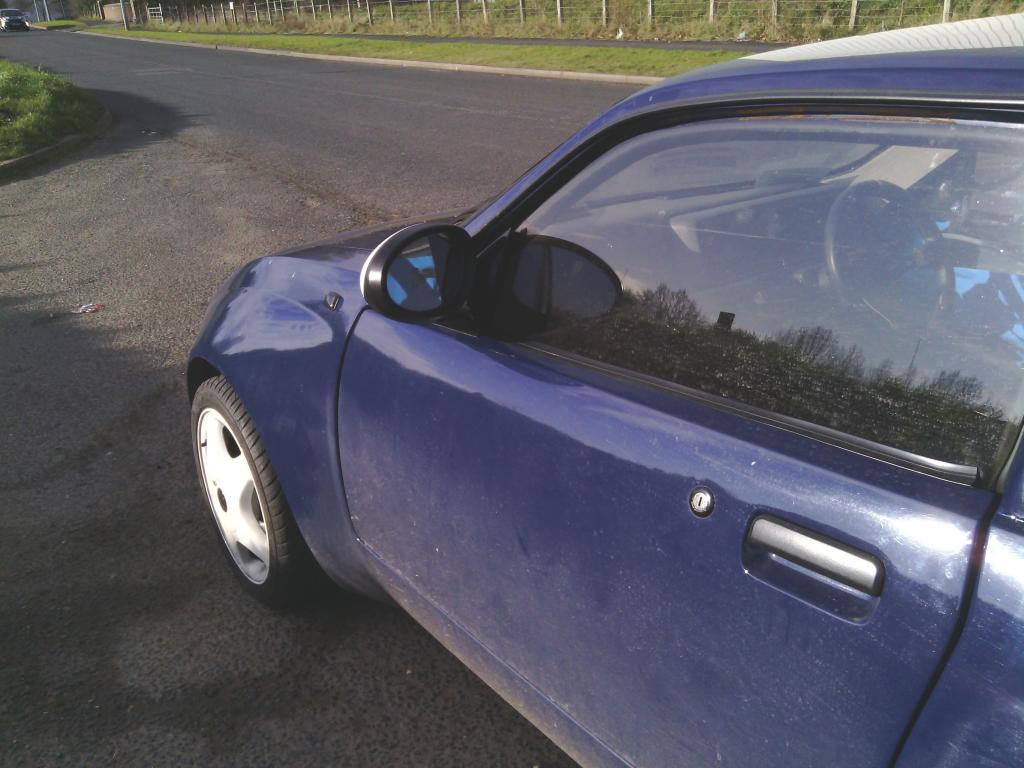 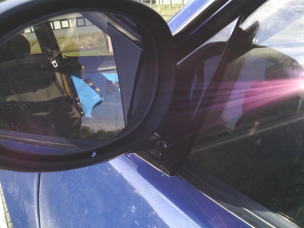 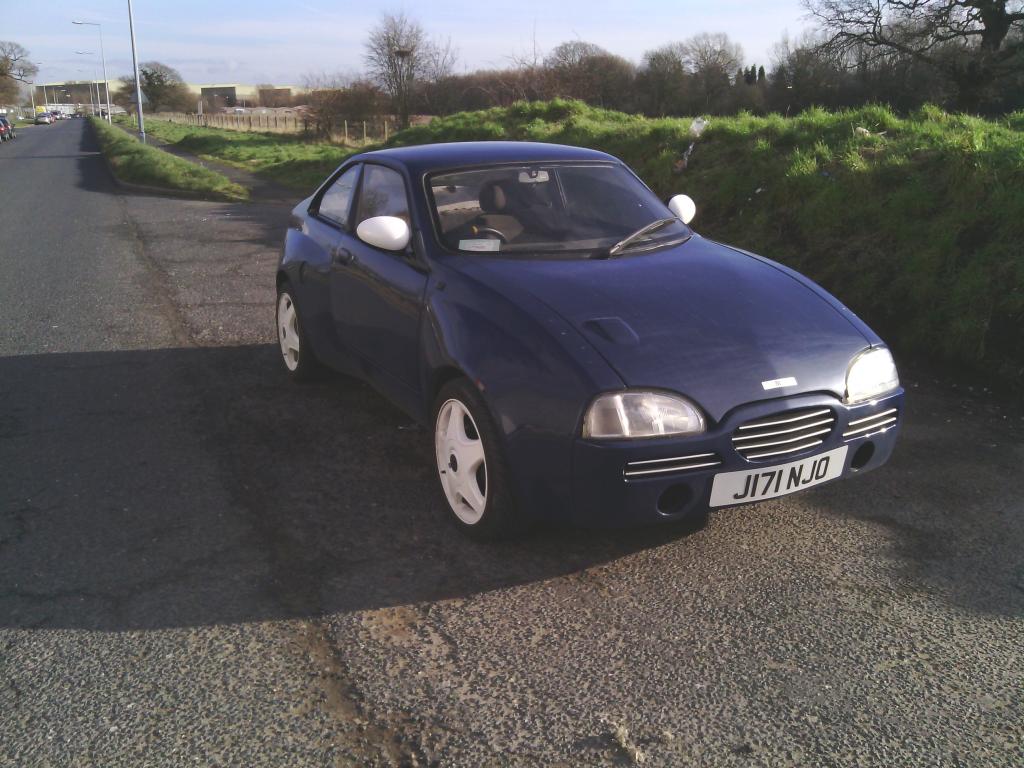 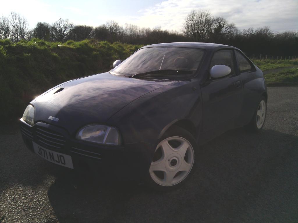 | ||
| Jin |
| ||
| Regular Posts: 159    | april 2015 mirrors and boot trim After 1 or 2 negative comments on the R25 mirrors looking way too big, and if I’m honest they had a point, 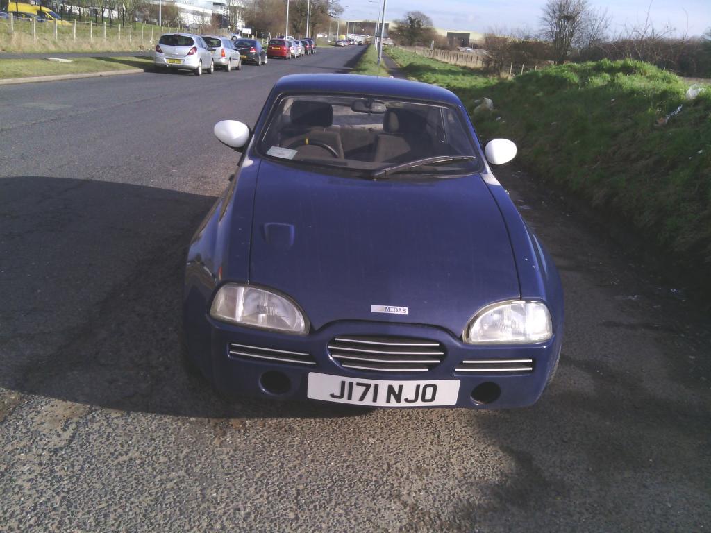 yet they look like small mirrors on a rover 25 I decided to change them, I looked about but all mirrors I considered were the same size as the R25 ones including those from a Peugeot 107 which you would think would be small, I even considered auxiliary 4x4 mirrors but doubt they would be legal, then I happened upon a chance encounter of 2 rover 75s parked close to each other, one pre facelift one post facelift, the facelift uses the mirrors off the R25 / 45 etc. the pre facelift uses similar shape but much smaller units, so a pair was ordered and the same process done, prime and paint and i decided to step away from white trim highlights and go for a more conventional but modern gloss black. fortunately I only had to perform minimal modification to get them to fit the brackets I made for the R25 units so that was easy – much improvement-pics in a mo. While on the gloss black theme, I was going to spray the boot / number plate trim black to tie in with the mirrors, but a closer inspection saw it to be rather ropey - the number plate lights were held in with wood screws? and the plastic slightly faded and cracked 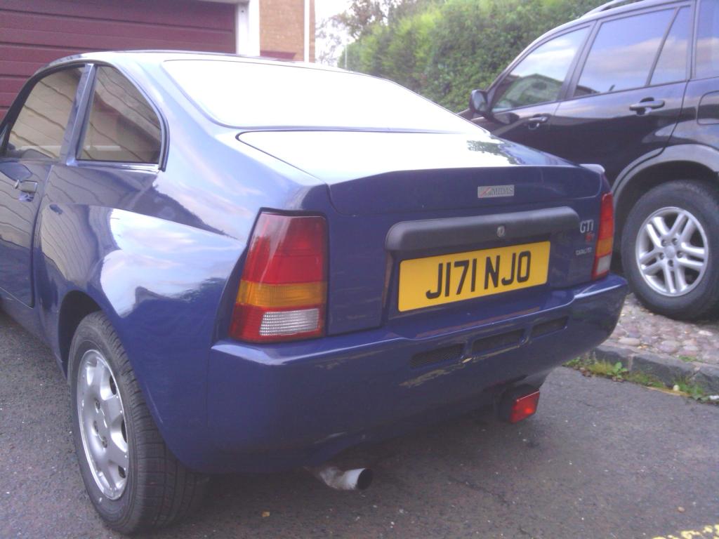 , so i decided to try out the rover 100 type facelifted trim, its slightly smoother and folows the contour of the actual bootlid better, 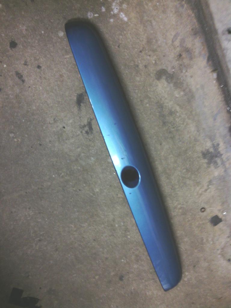 painted up 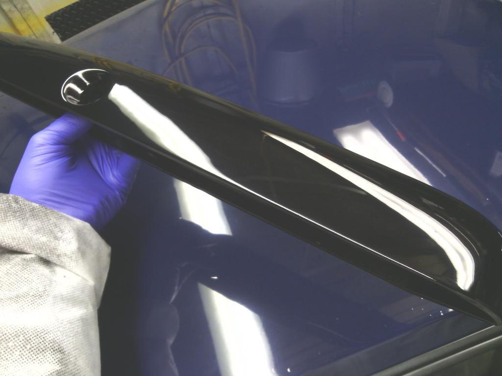 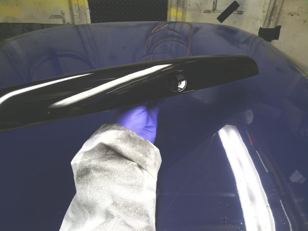 fitted 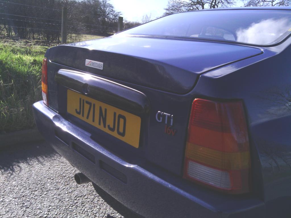 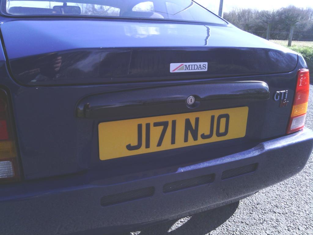 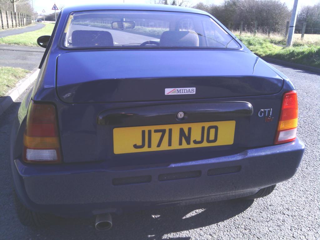 tided it up a tad 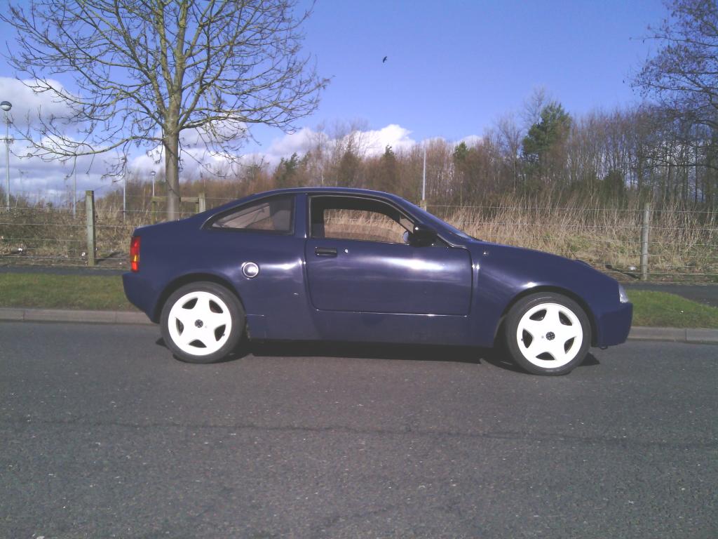 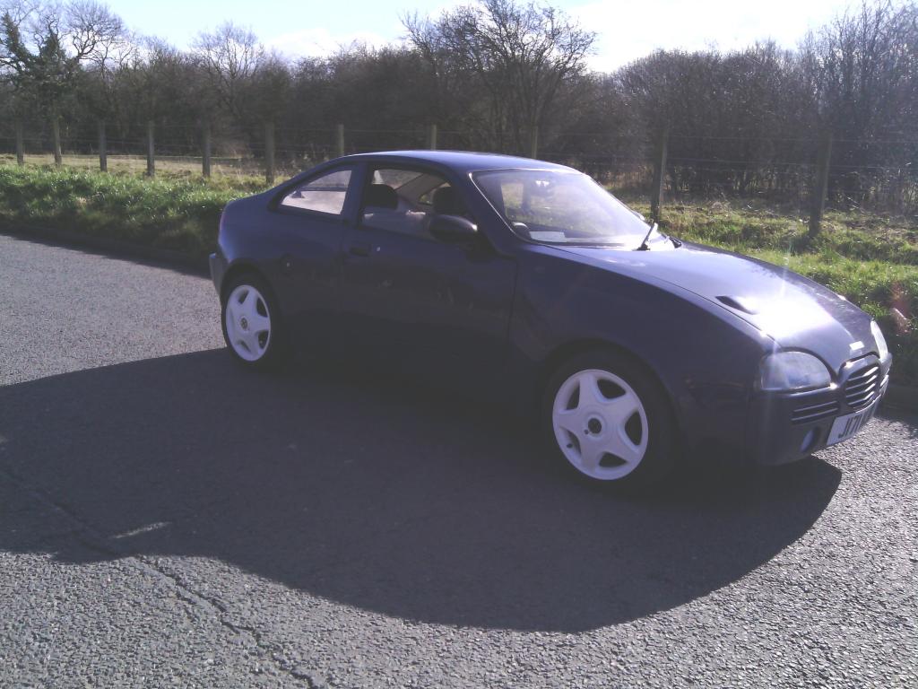 next on the list (and it was a must) interior lighting. for some reason the car has gone 20 years with no attempt at interior lighting, although not essential, i do like to be able to locate the barley sugars of an evening slightly easier. i was and still am toying with doing something creative with EL panels at some time but the cost is a bit scary so for now i discovered the MGF has cortesy lights built into the rear view mirror, so i got my hands on one which also helped since the origional mirror dropped off into the murkey depths of the footwell some time ago 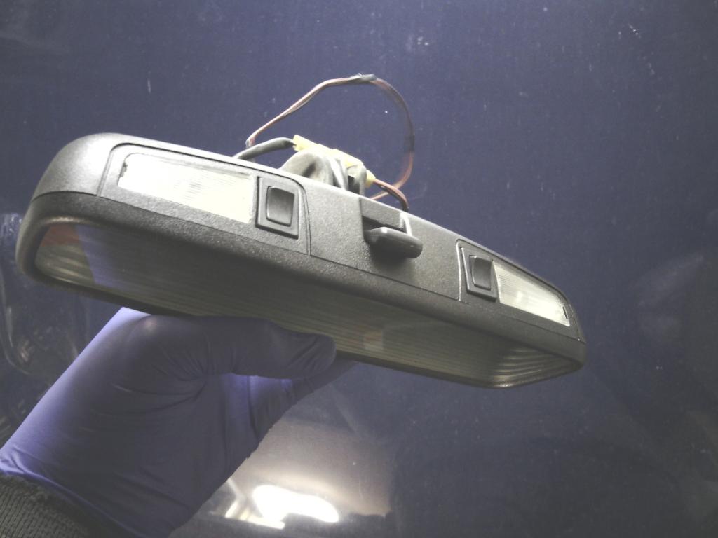 and all wired up, much better now and the rear view is beter too. 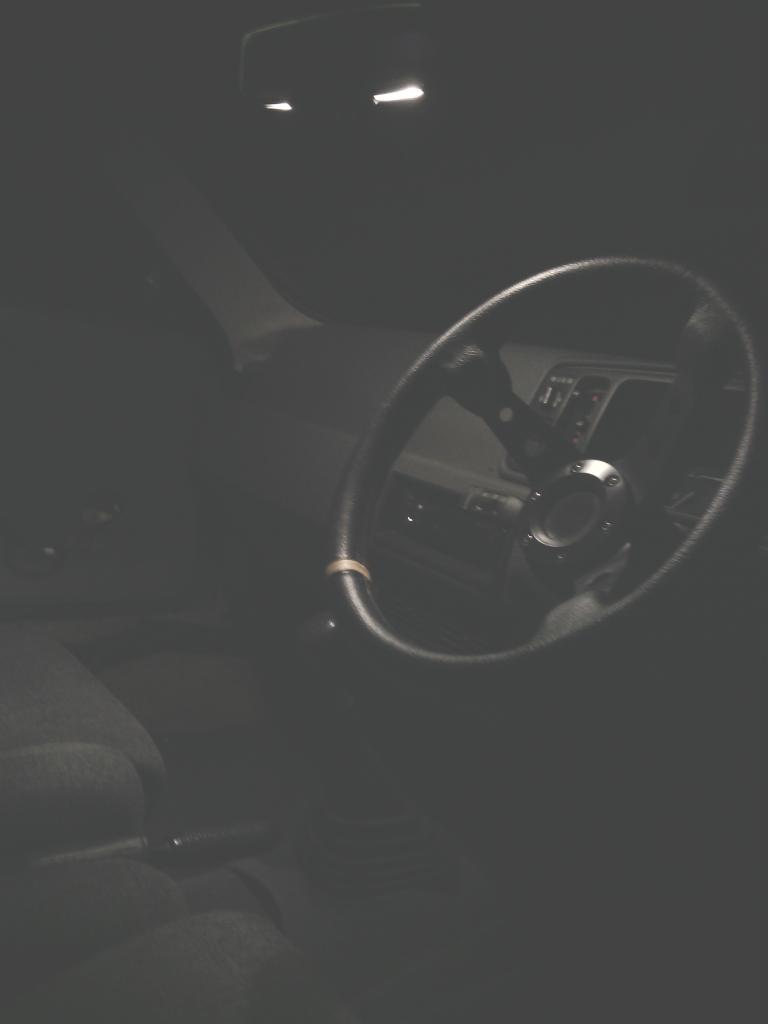 Engine bay freshen up One thing I liked about my Quantum was the engine bay was so clean you could eat your dinner off it, I’d not set out to do that but it was a consequence of rebuilding the car from the ground up – and I liked it. Although I’m not swapping the engine in the Midas just yet I don’t see why I can make the engine bay a more pleasant place to be in the mean time, the rad hoses were well past their best and constantly seeping anyway so now seemed a good time. First job was to pressure wash the entire engine bay and engine, I’ve not used TFR before but the Swarfega Powerwash brand worked fantastic, I could not believe the amount of crap that got washed off, with the car raised I did underneath too, years of crud got washed away leaving all that was left behind to look as new as could be expected Onto the rad hoses, All the rubber and metal pipes were degrading rapidly and tweaking up the jubilee clips became a regular part of life, 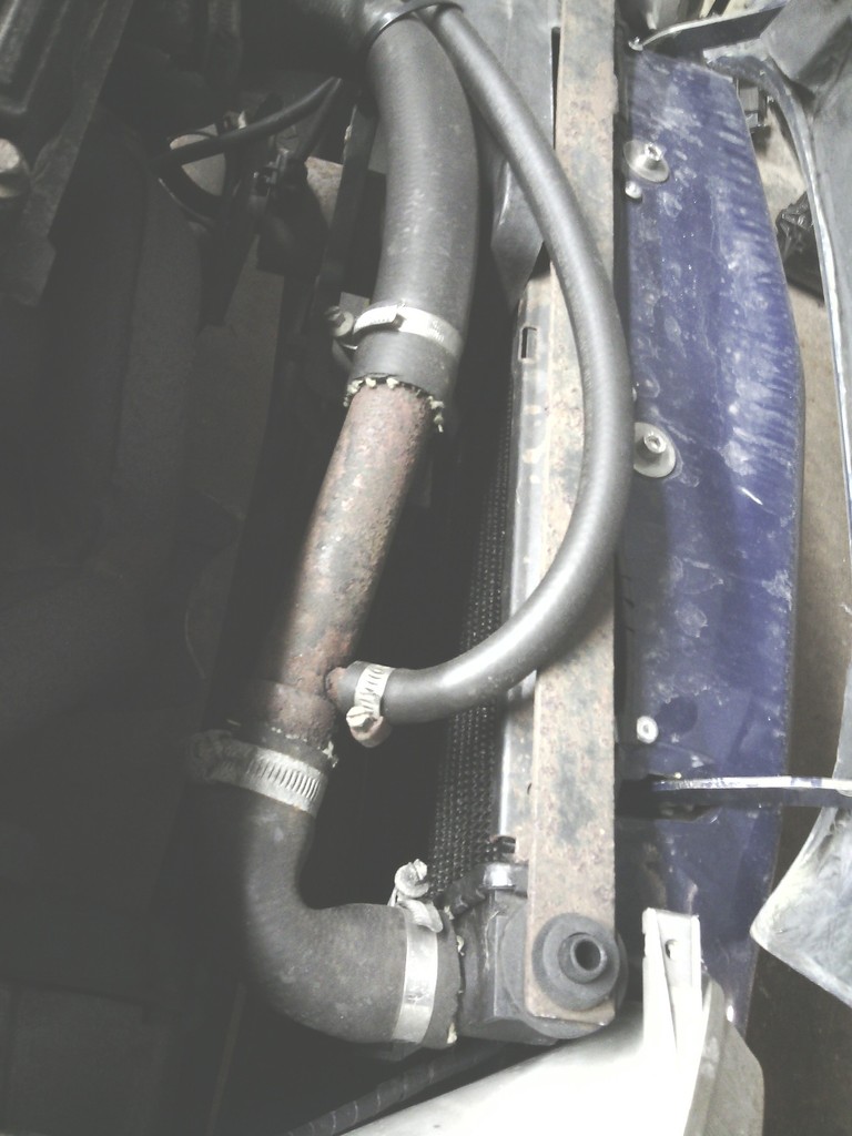 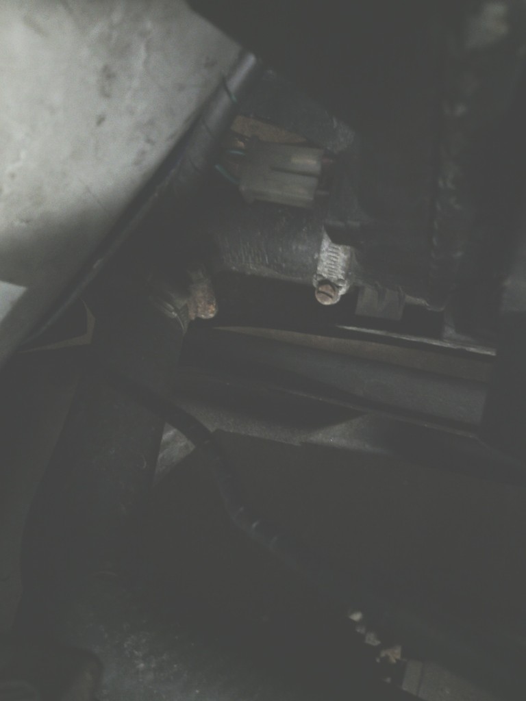 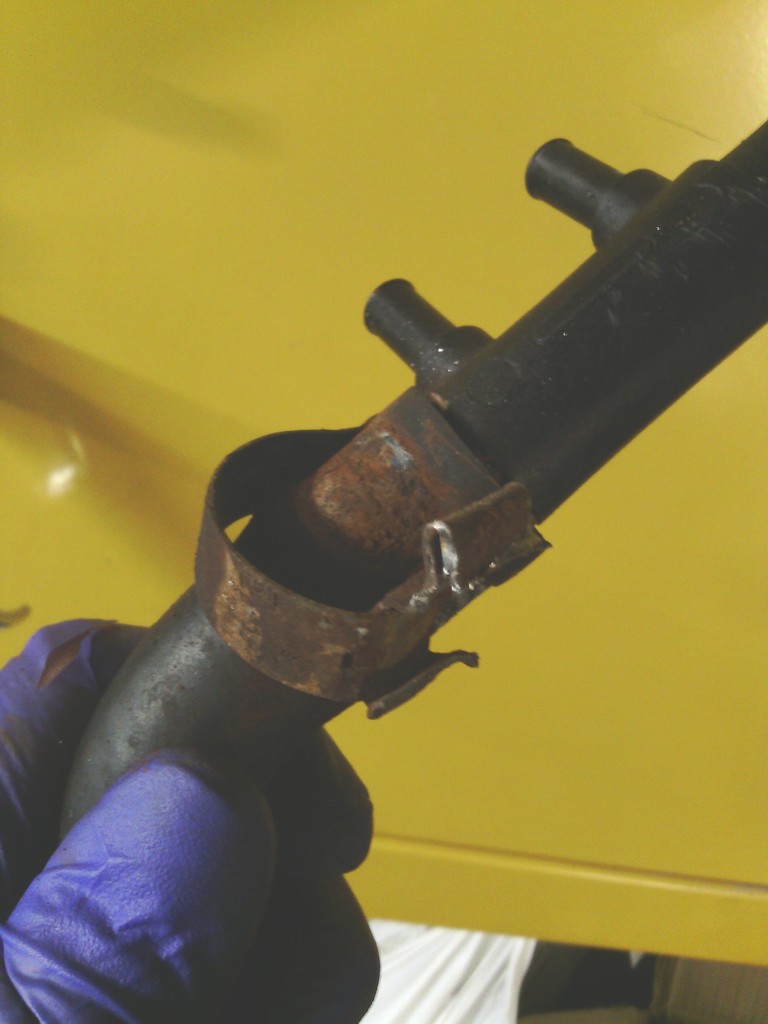 so I made a new top hose from copper pipe and a brass tail 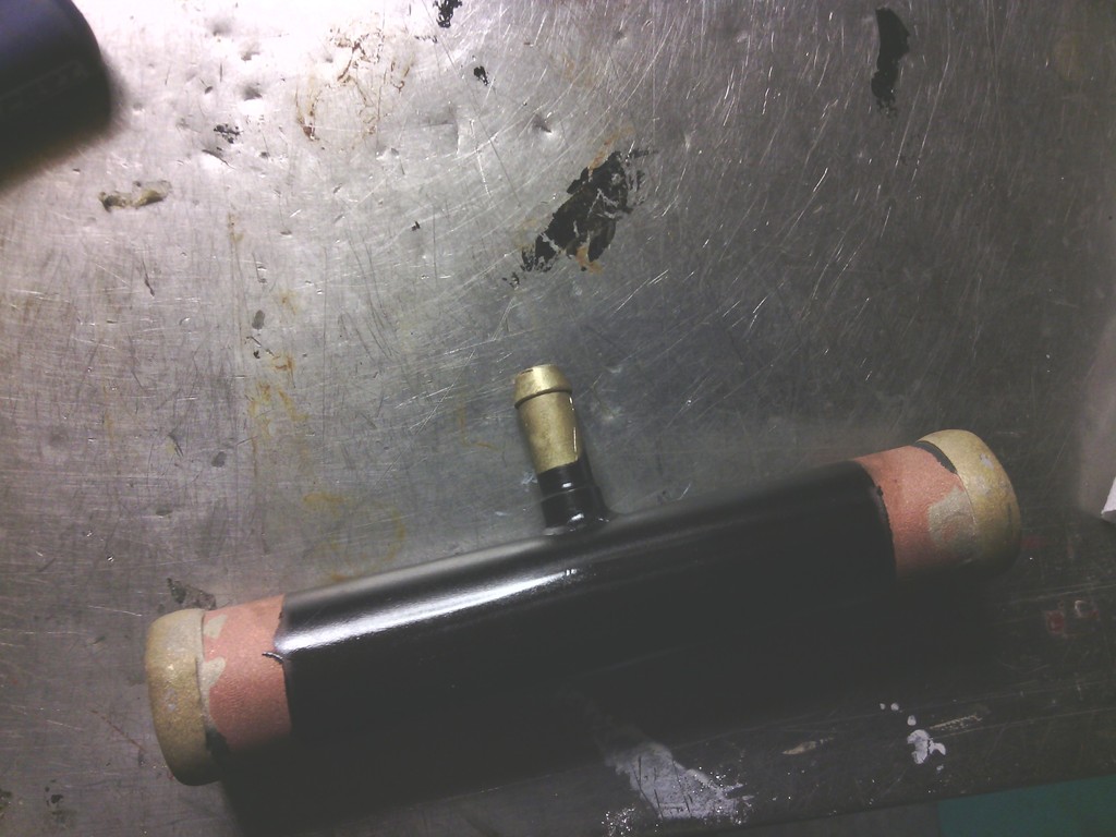 And bought a new old stock rear metal pipe that runs from the stat round the back of the block, 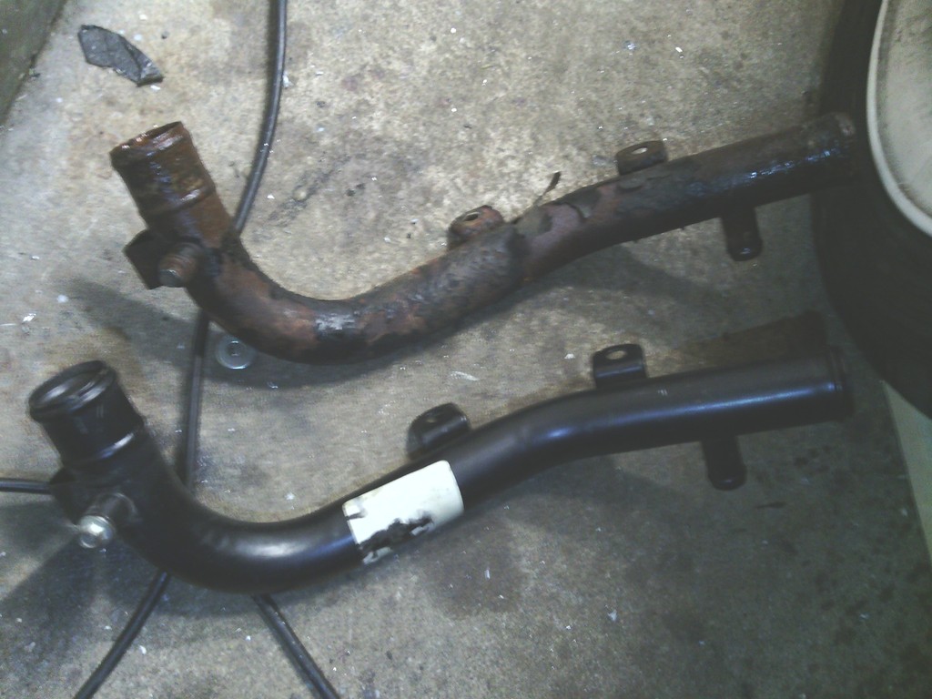 all rubber pipes were measured up and silicone hoses ordered for their replacement, 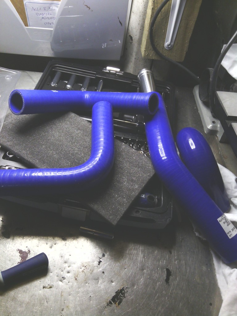 The day came to do the job and all was going well until I got to the rear metal pipe from the stat, its 2 x 8mm bolts were rather tight, the one nearest the flywheel came out eventually once cracked but the one mid way round the back of the block was so tight I couldn’t budge it, I could only get at it from the cam belt side with a 1/4dr ratchet too which didn’t help, once id exhausted myself to the point of passing out trying to budge it I had a brain wave that would either see it freed off or sheared, at this point I didn’t care which I could see (but not reach) the ratchet handle from between the inlet manifold ports, so I looped some of my strongest cable ties together in a chain and fed it down and round the ratchet handle, then with a length of wood resting on the rocker cover looped through the end of the cable ties I could use is to lever up the cable tie chain against the ratchet handle and by pulling from below with my other hand it cracked off – bingo! But each turn was just as tight as the pervious until it had freed enough to do away with the wood lever and use my right hand instead, so using both hands above and below I could move the ratchet enough to rotate the seized bolt enough to slowly unwind it progress was very tedious but progress non the less, feeling a bit smug with myself for finding a solution to the problem I got a good rhythm going on the still very tight bolt and all was going well until WHACK!, the cable tie chain slipped off the ratchet handle and the resulting pull force with my right hand was transferred to my jaw, I’ve never been hit so hard in my life and did feel somewhat shaken. After a brief rest and pep talk to myself I carried on somewhat more carefully than before, thinking to myself just how long does this bolt need to be? All going well then….. Another punch, in the eye this time. At this point I had to give myself a bit of a talking to, This is my hobby, I’m supposed to enjoy it, and here I am late at night standing in a cold garage repeatedly punching myself in the face and almost bringing myself to tears – why oh why did I not follow a much safer pursuit such as sky diving or deep sea shark fishing? Anyhoo with the worlds tightest M8 bolt finally out the head I could refit my new pipe and plumb it all in, Next on the list was the rad mount, or lack of The original rad location was too low down to fit he sexy spot lights I got from Neil when buying the car – the bottom hose was in the way – not too much of an issue as I wold have to raise the height of the rad anyway since there was no bottom mounts for the rad, it just sort of flapped about, you can see the impression the bottom rad legs had made in the fiberglass aftr years of not being properly supported. 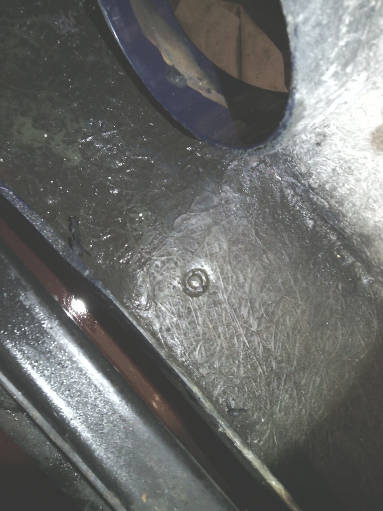 So some 25mmx25mm ally box was used to make proper mounts 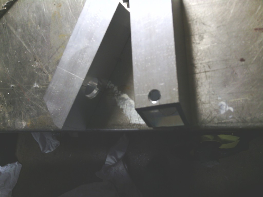 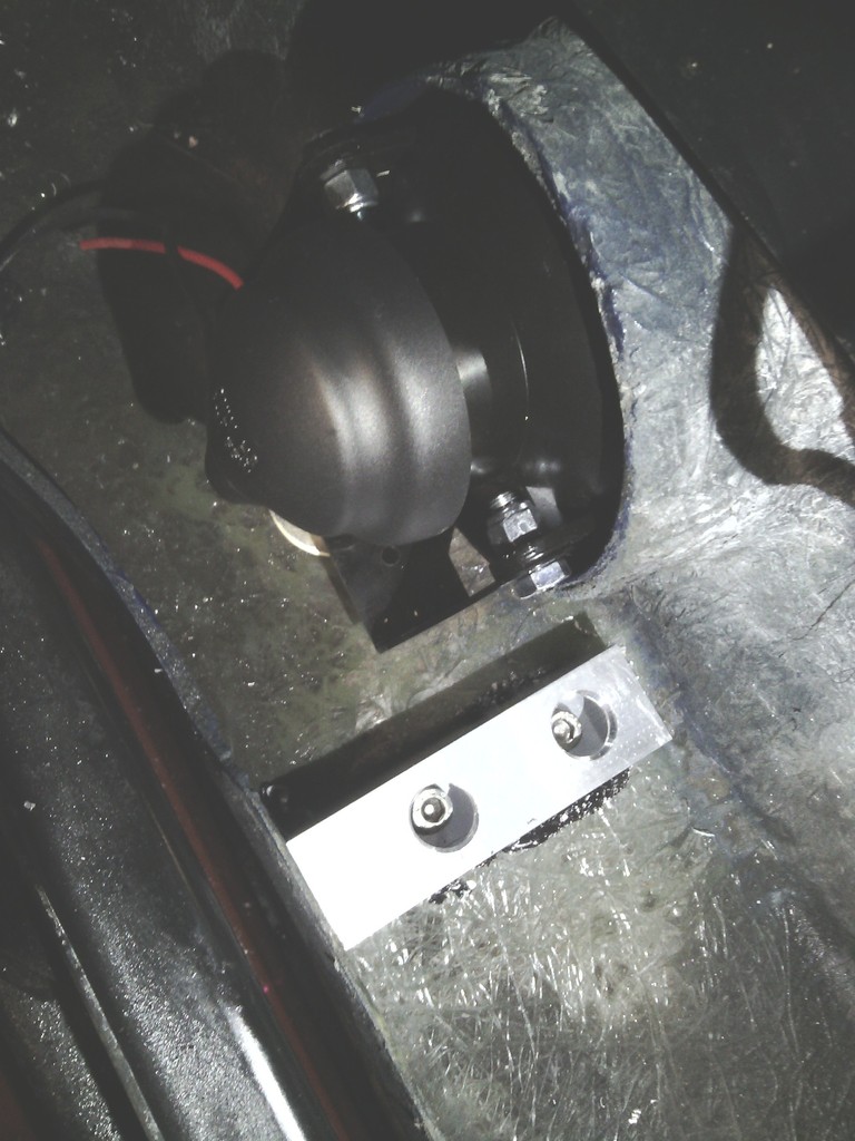 And now the rad sits higher to clear the bottom hose and the rad locates secure in the bumper too – nice While down there I properly fitted the fog lights by making proper brackets out of stainless and aluminium – the old ones were just bonded in 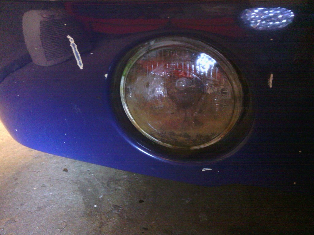 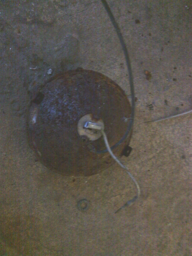 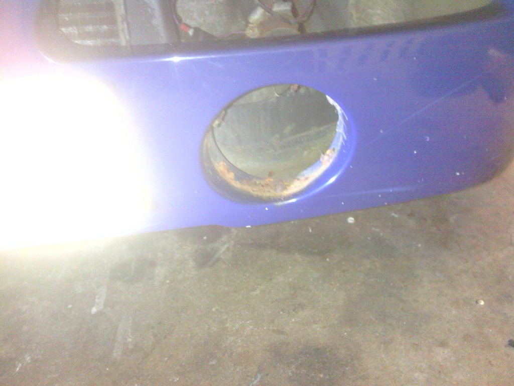 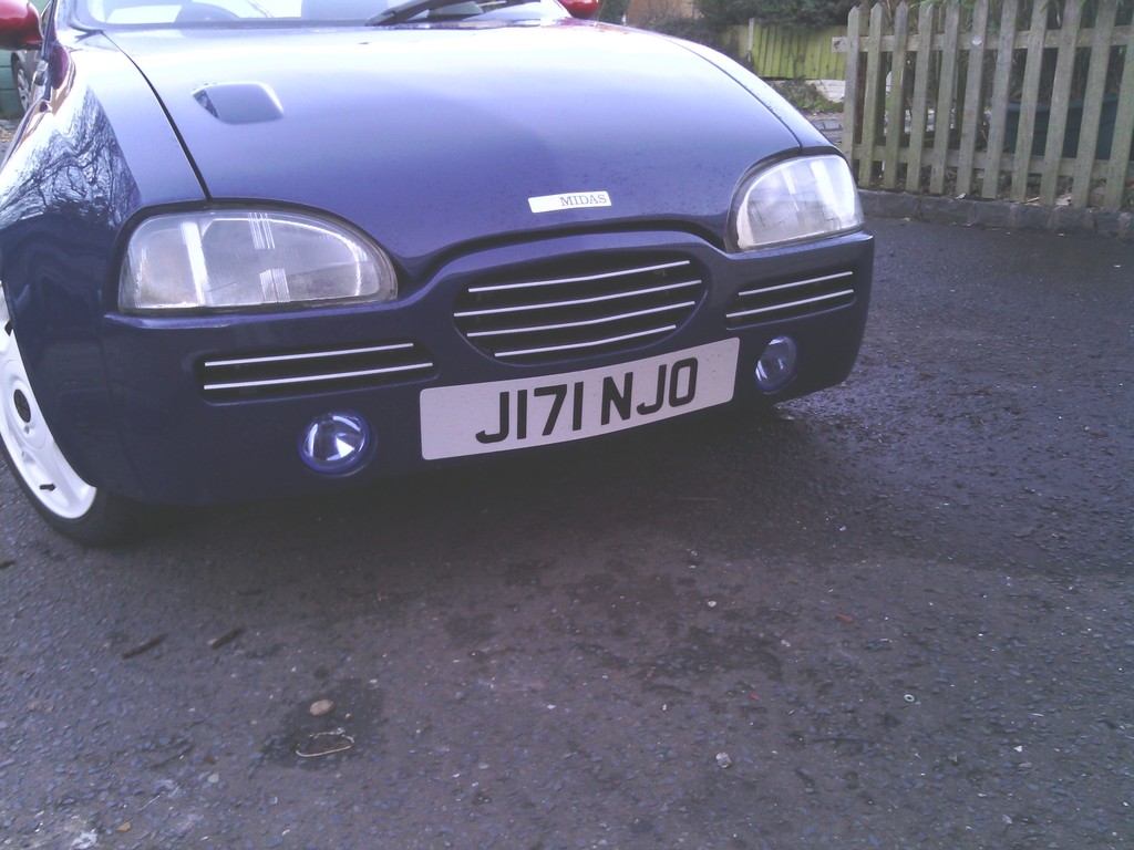 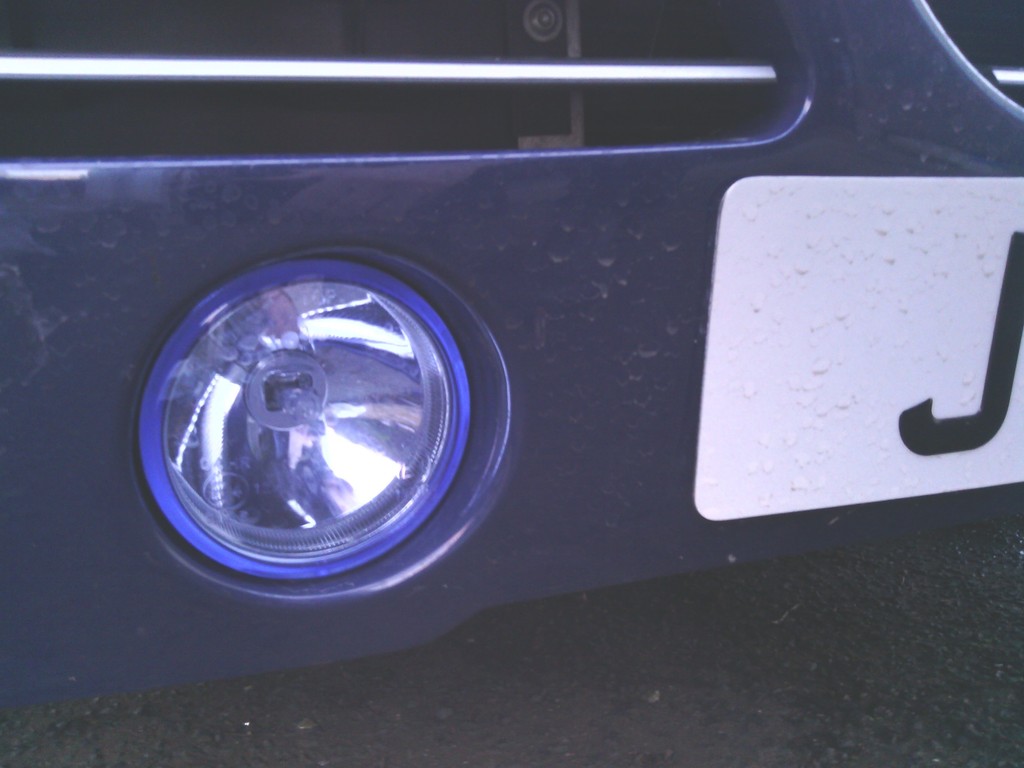 With the rad mounted at the base and slightly higher too, the top mount didn’t fit, just as well as it looked rubbish. 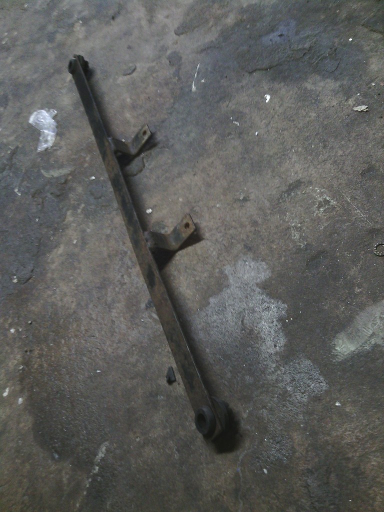 A nice bit of 3mm ally sheet was ordered 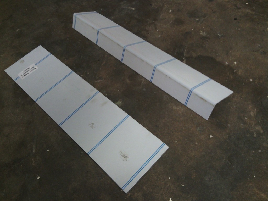 And bent to fit, after some fabrication and some riv-nuts all was well with the world once again 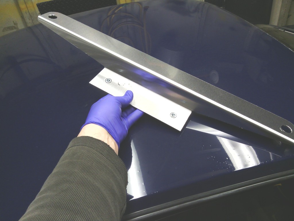 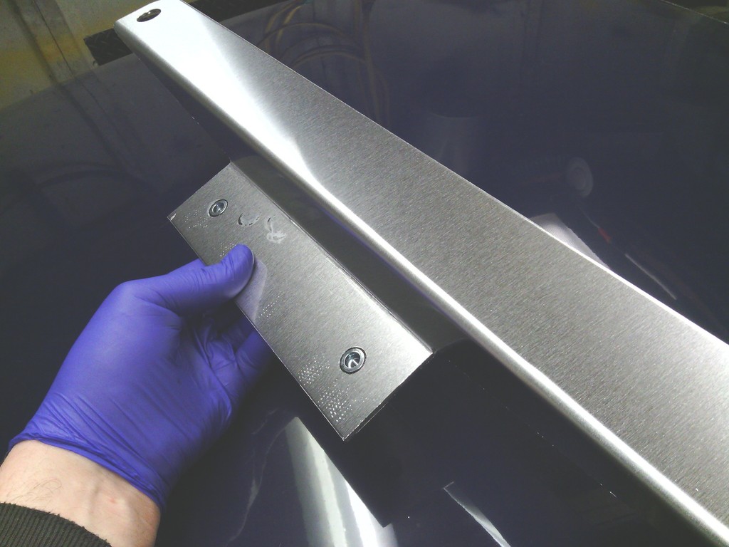 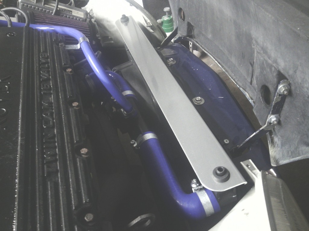 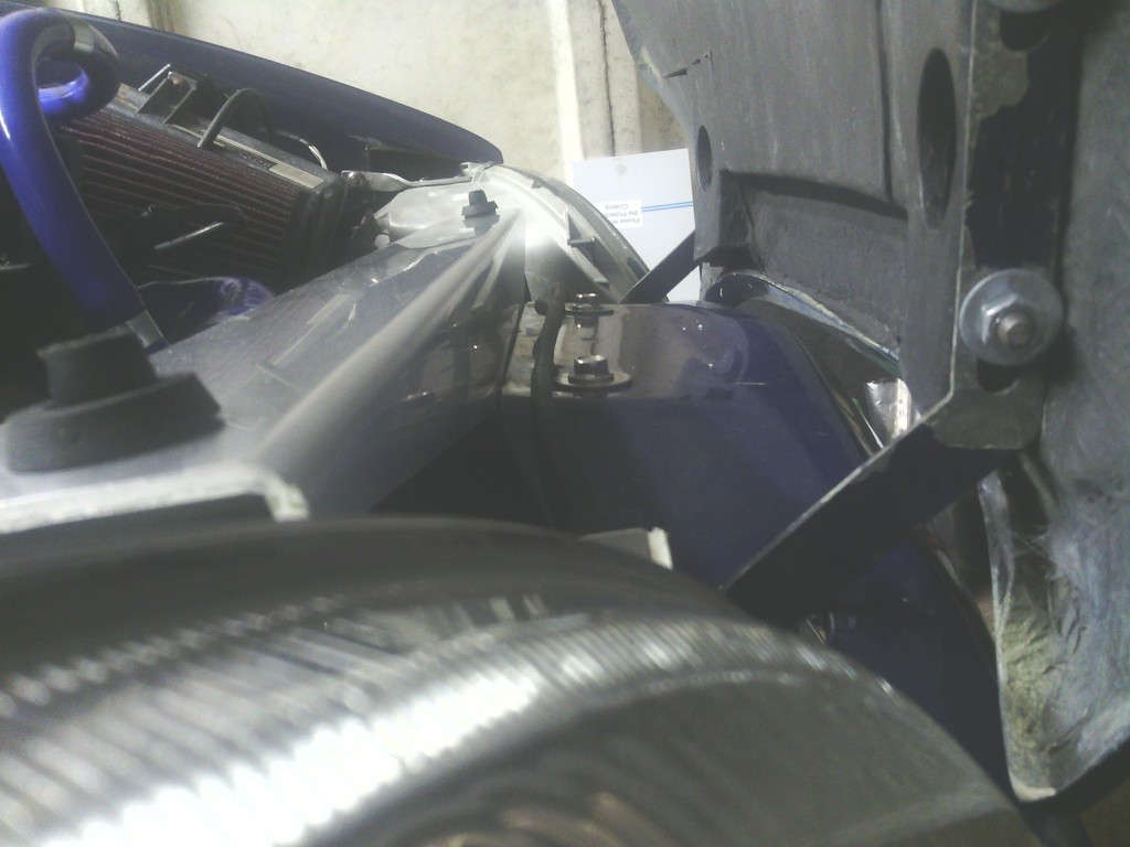 The reservoir bottle got the old bleach and rice trick and it came up like new 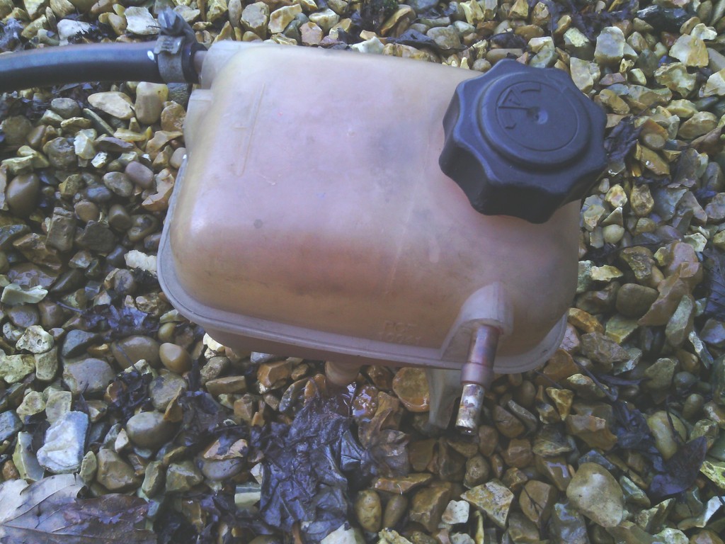 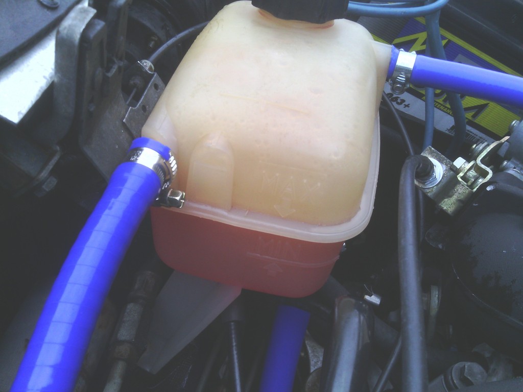 And while in the area the mount for it and the fuel filter looked proper shonky too, the mounting bolts were rusted solid yet loose at the same time so water just poured in, 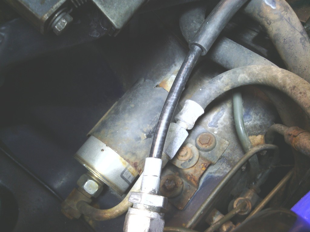 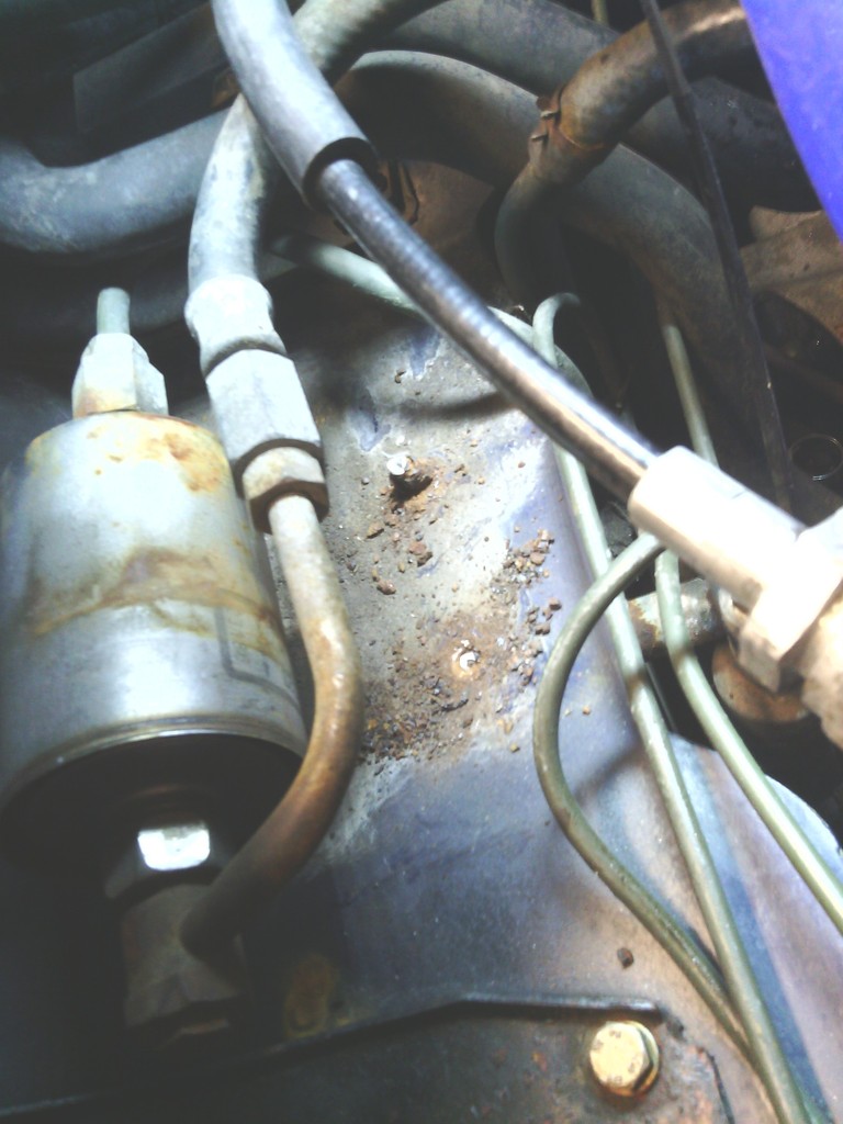 A new base was made from 10mm thick aluminium, this was drilled and tapped with M6 stainless studs and bolts, this whole assembly was bonded on to the bulkhead with polyurethane to seal up the holes and the studs were thread locked in to seal them also, 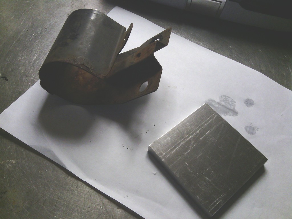 A new stainless P clip for the filter was ordered and all bolted up the finished job looks much better, it would have been a nightmare to change the fuel filter with the old bracket since I had to drill the mounting bolts out. 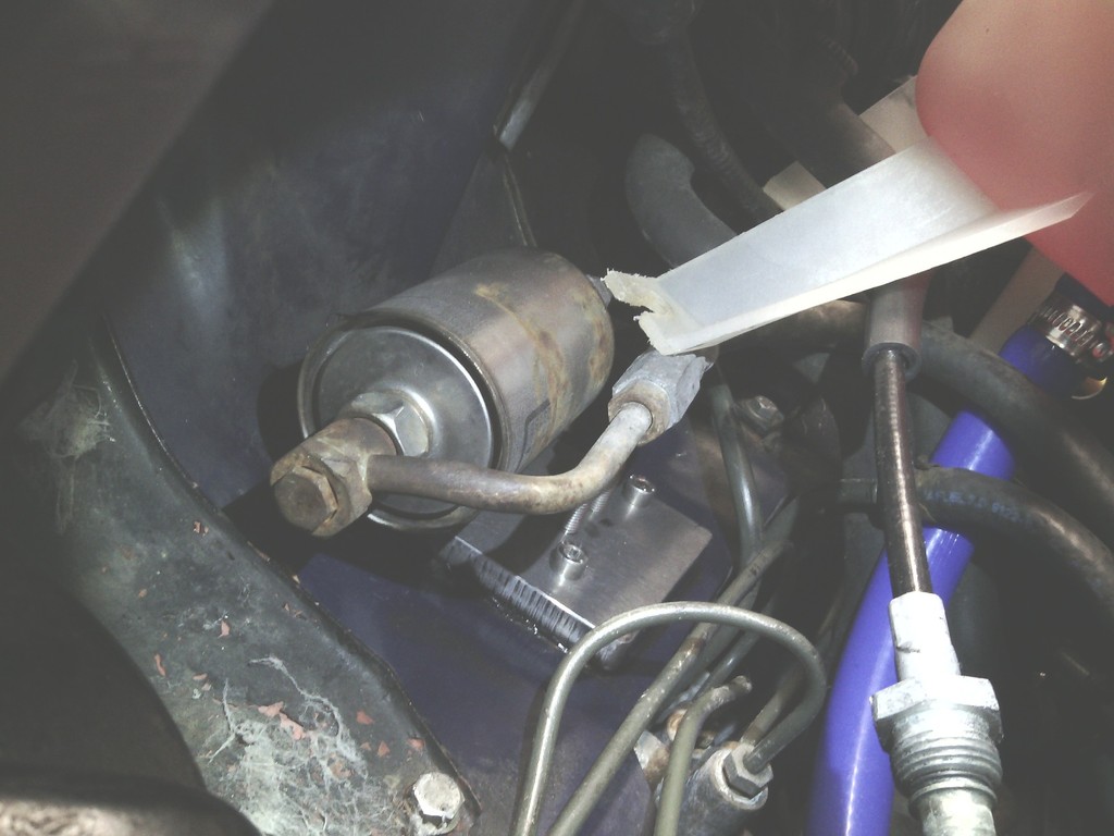 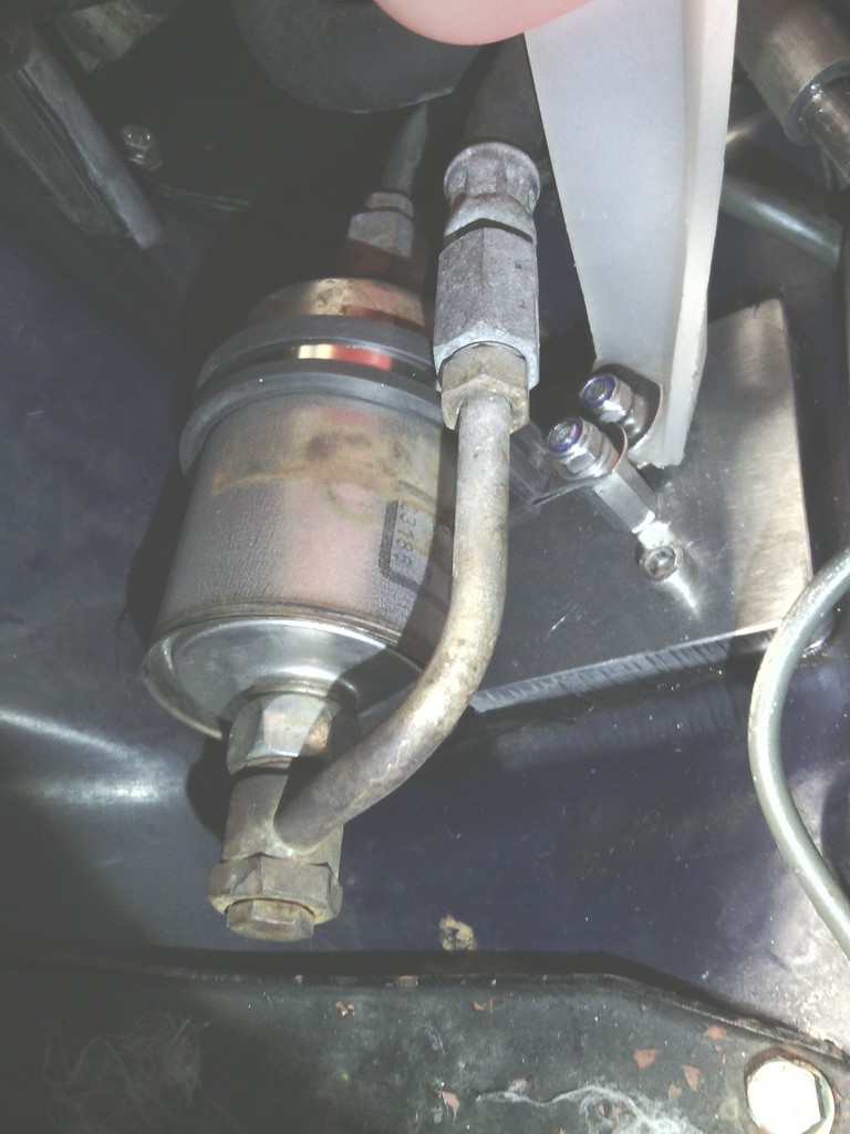 then the remaining hoses were fitted 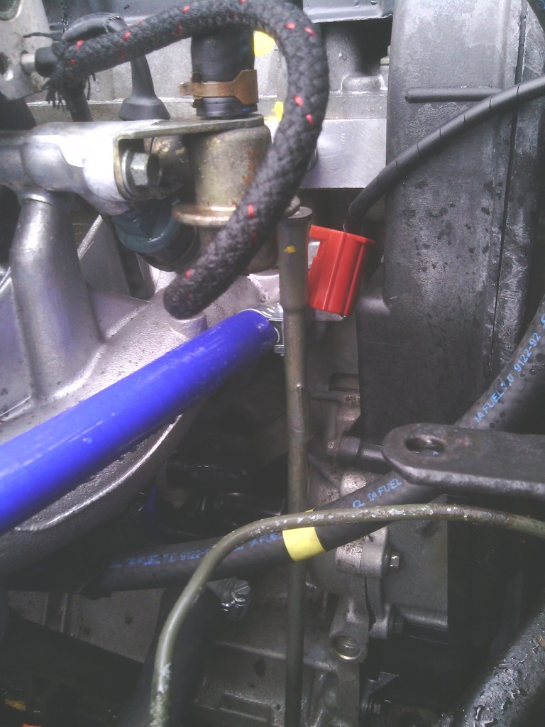 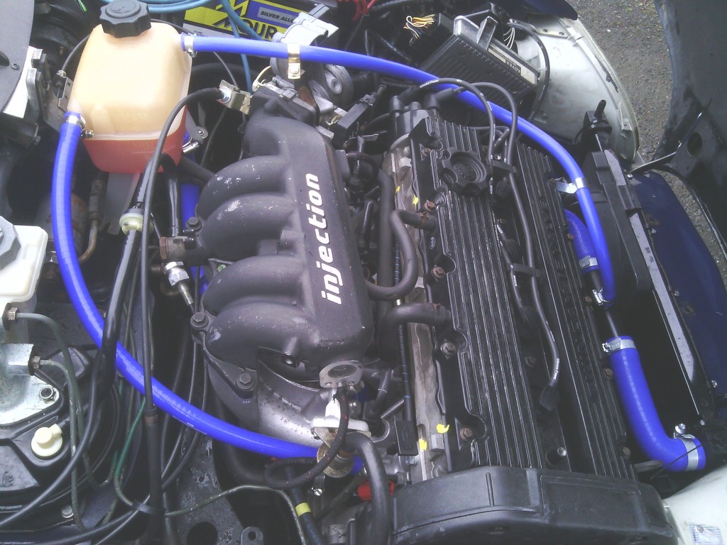 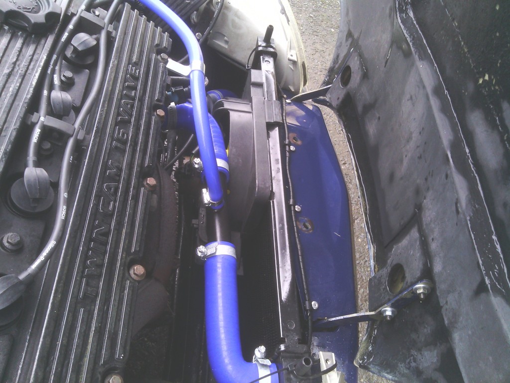 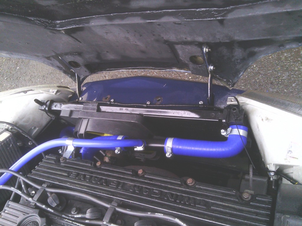 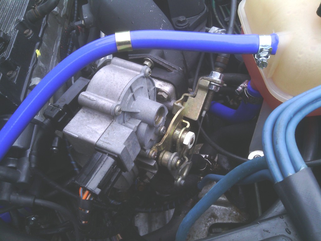 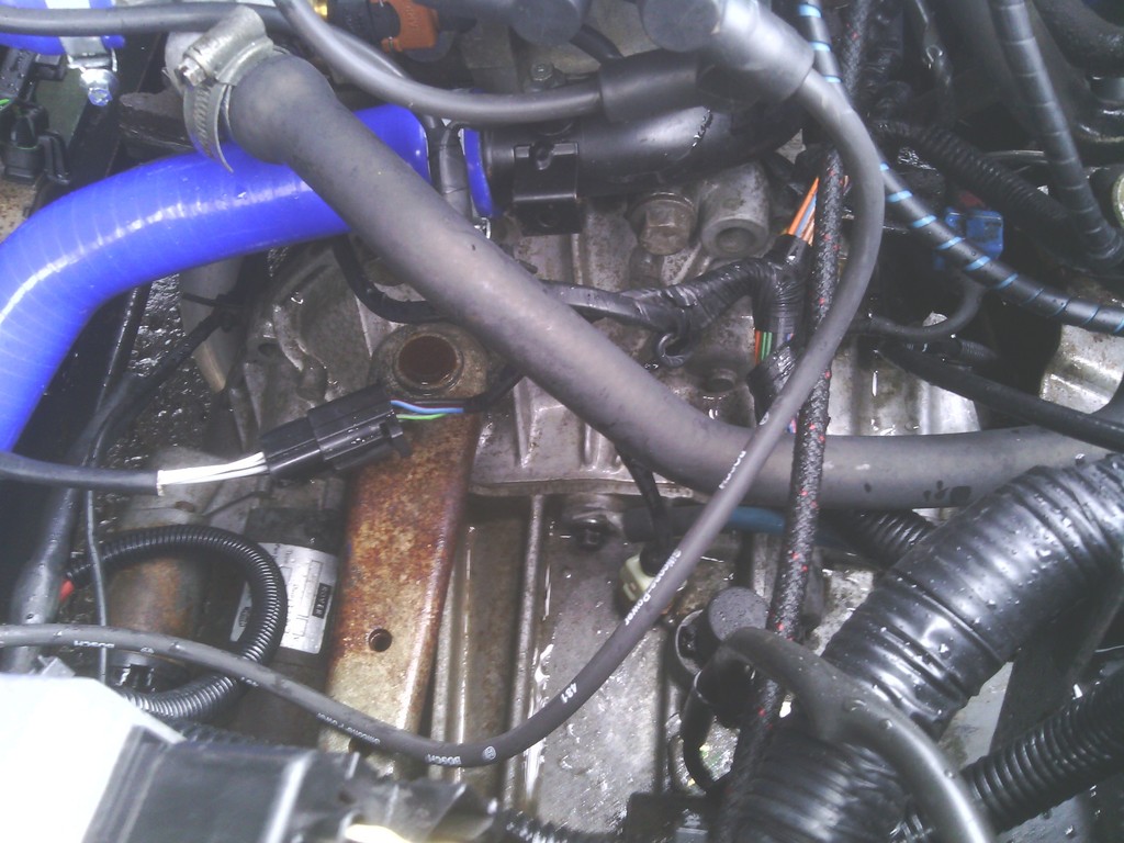 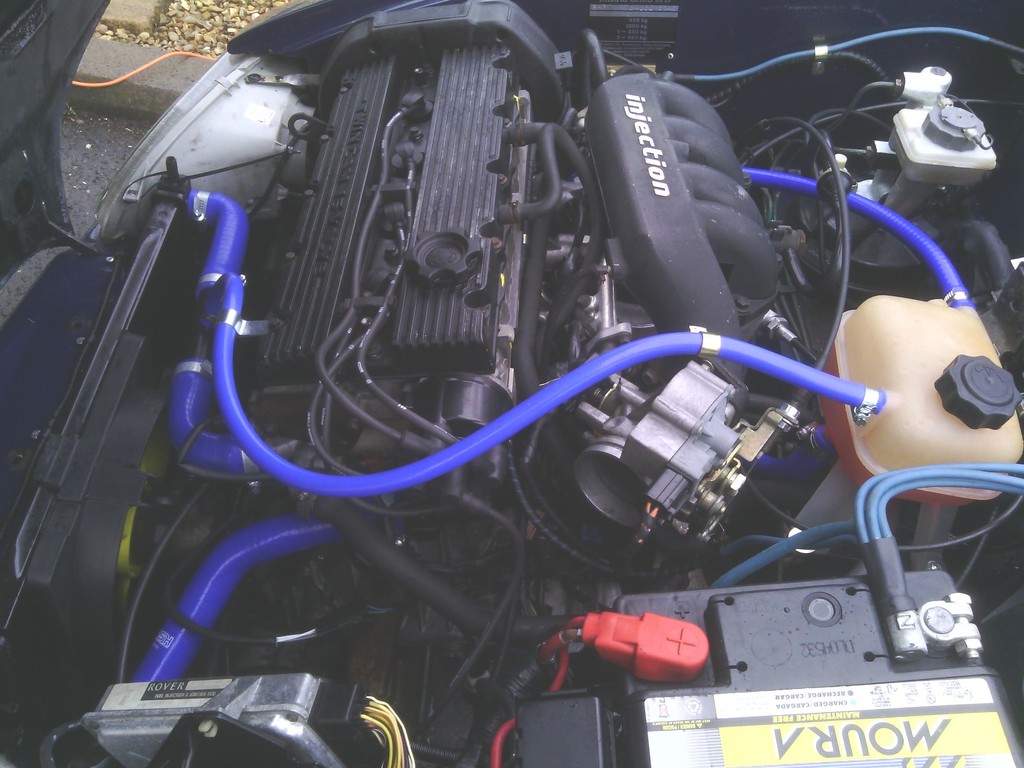 The wiring loom didn’t inspire confidence either so I set about checking and replacing where needed, the whole ECU loom was picked apart and tested, most of it checked out ok 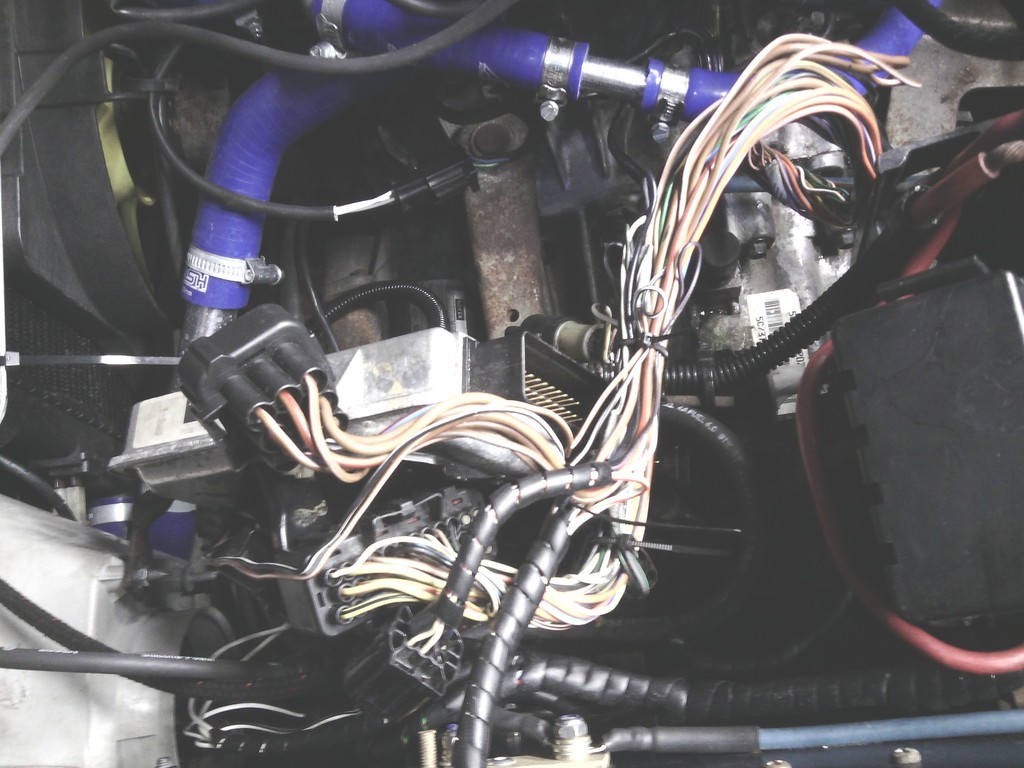 I found where the fuel cut off switch used to be 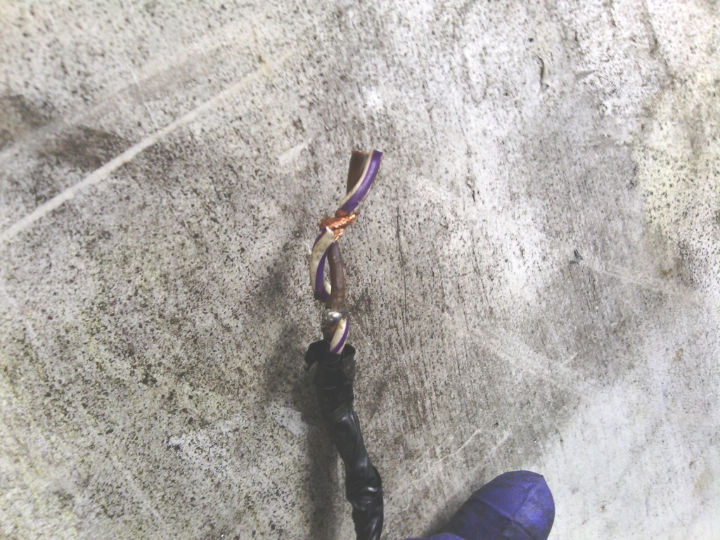 Twist n tape! – wiring repairs obviously not a strong point on this car…. Once that was taken care of I replaced all the engine management sensors for brand new since prevention is better than cure, it cost a bit but it was the right decision especially when looking at the crank sensor 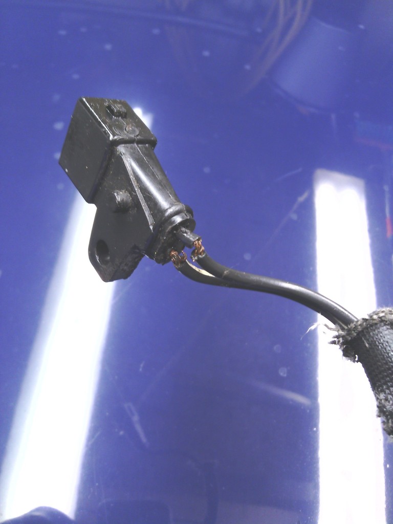 About 2 strands left per cable and once this breaks the engine dies. All this tidying up got me on a roll, the engine bay was comming on but it lacked a certain something 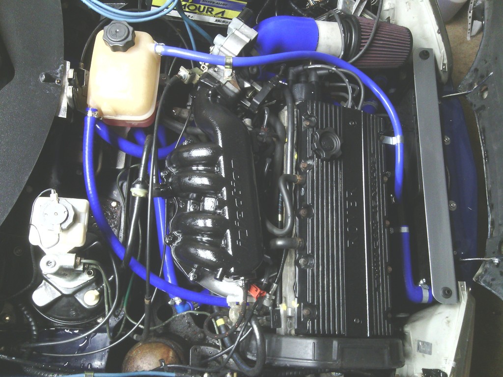 so I ordered a replacement rocker cover off a Freelander and set about reworking it (handy all K series are identical externally) I shot blasted it 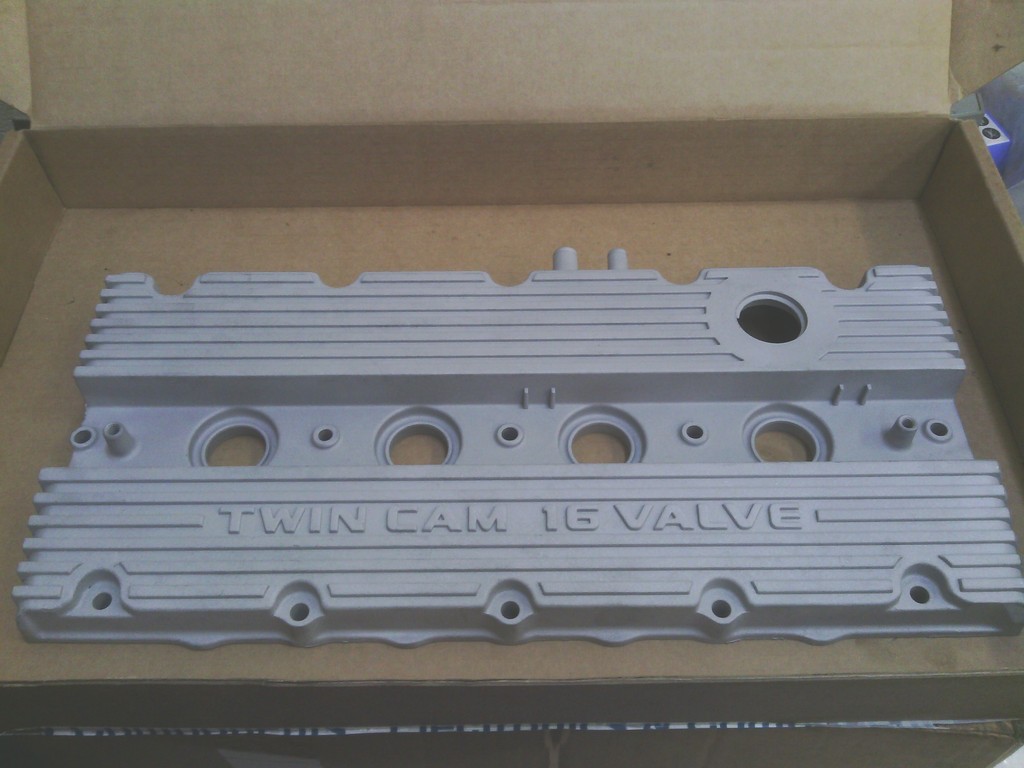 Painted it gloss black 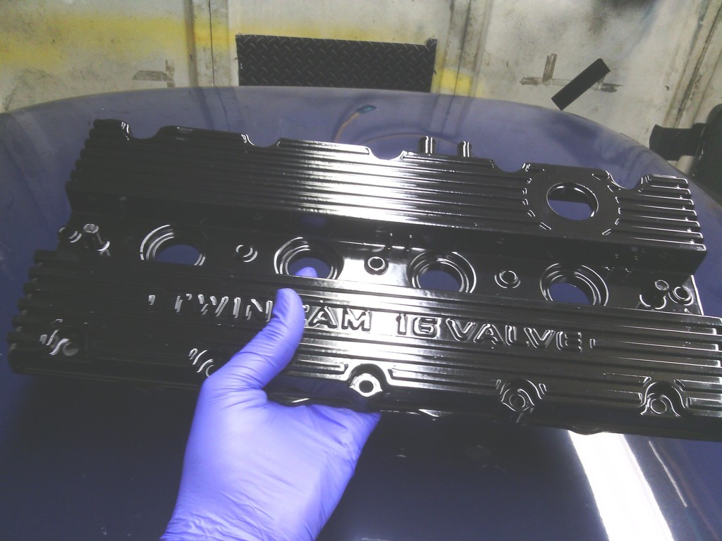 Then sanded off the raised lettering to reveal the “twin cam 16 valve” writing, it took some doing since not all the letters are the same height so a fair amount of aluminium had to be sanded back to keep it all even, the finished result looks fantastic 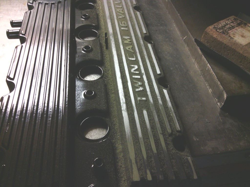 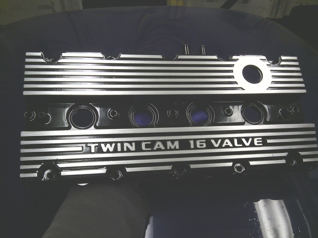 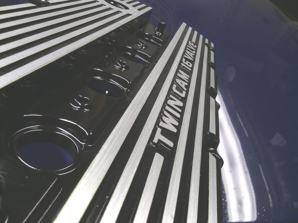 And I did the inlet manifold the same too While I can the rocker cover off I could see the cam shafts were in exceptional condition with no signs of wear whatsoever so that made me feel slightly better for giving myself a black eye earlier in the week and a compression check revealed the engine to be even and very healthy across all cylinders, that will do for now.. Only jobs left to do under the bonnet now is to do away with the rattly bonnet stay in place of a pair of variable pressure gas struts, and to also solve the mystery of the bodged fuel pump wiring, jobs for another day… 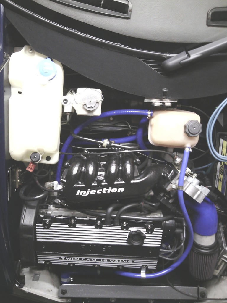 | ||
| Jin |
| ||
| Regular Posts: 159    | APRIL 2015 Since fitting the wheel arch extensions it became more apparent just how much wider the front track is compared to the rear, for some reason the front track is 2" wider? So I measured up for spacers and found 15mm to be ideal to even up the arch to tyre clearance, so bought 16mm - naturally. 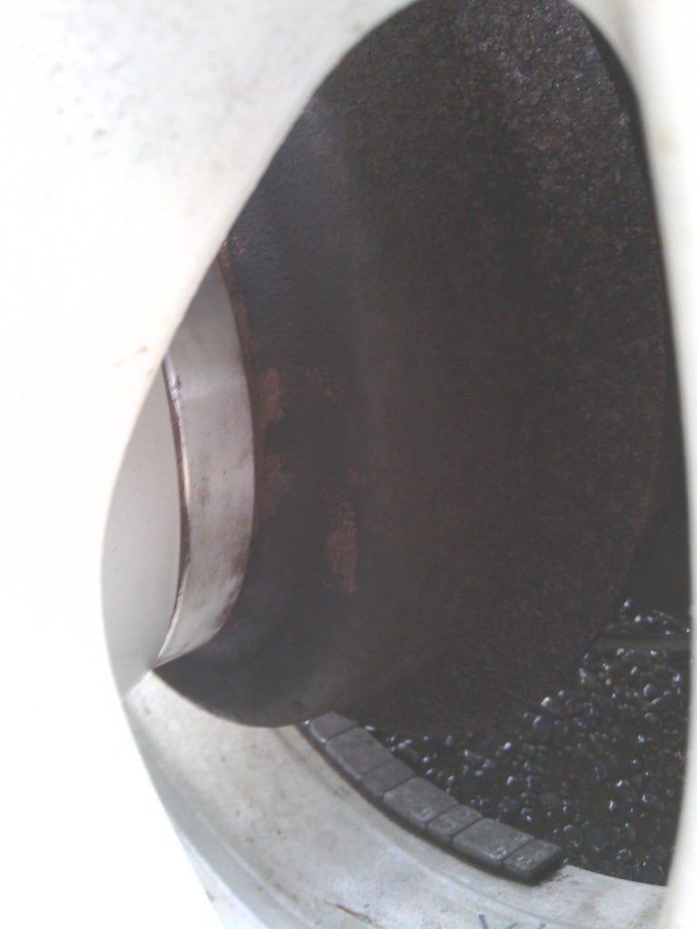 Comparison side to side 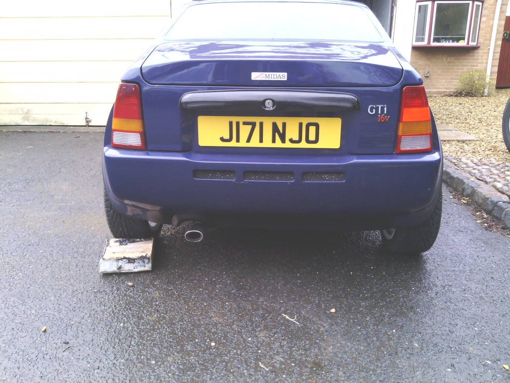 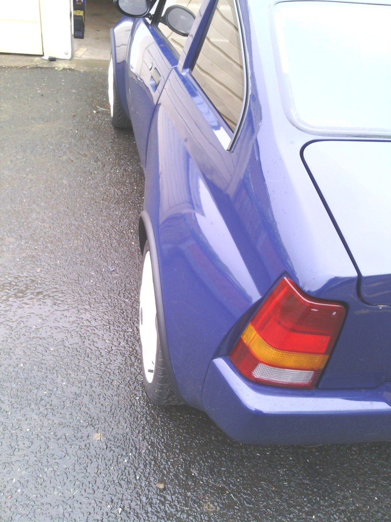 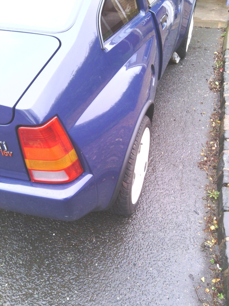 Since the rear now looked much better and the cars inherent skinny arse stance has now been improved I decided to give the front end a new look by utilising a garage door seal on the bumper base as a spolier,,then since the weather was very nice, now seemed to be a good time for some before and after pics especially since I gave it a wash and polish. Before 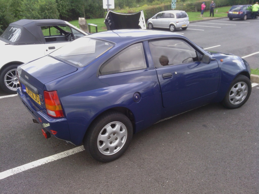 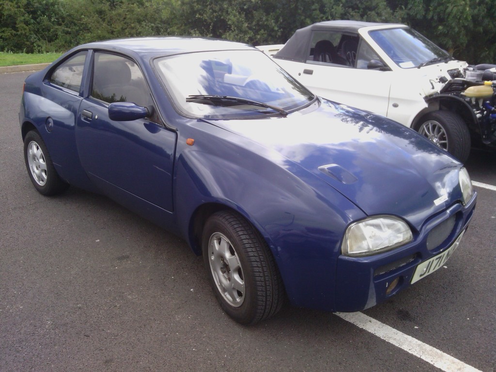 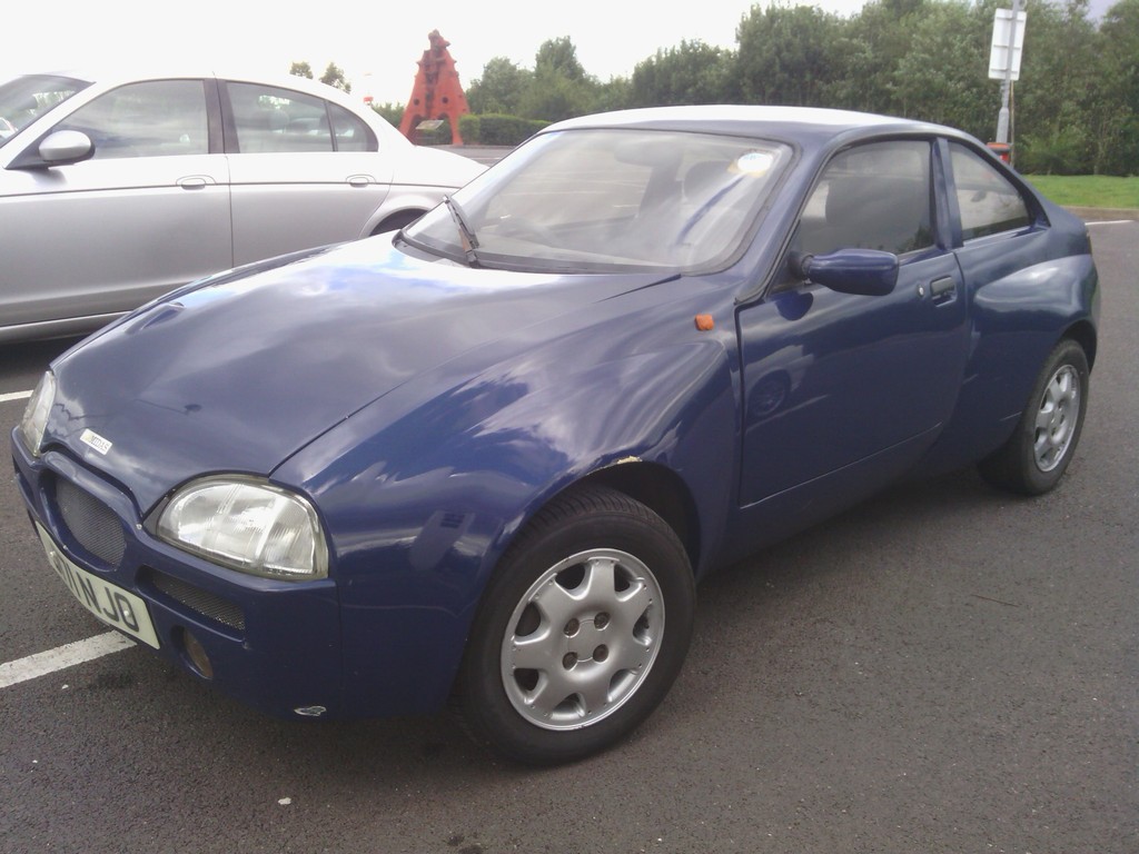 After 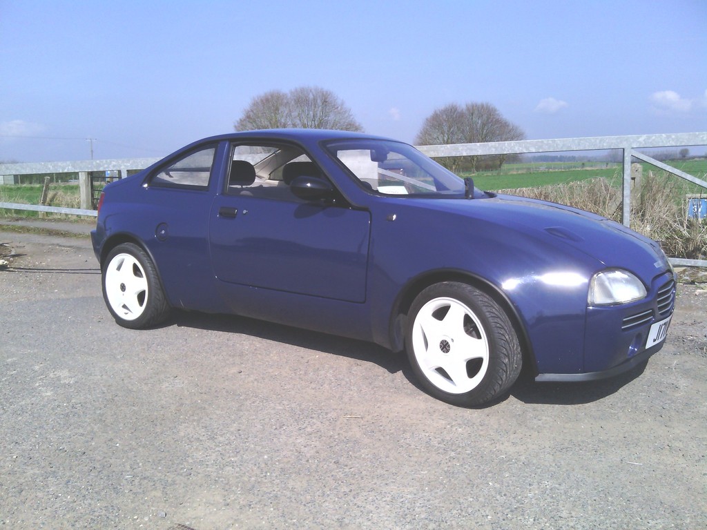 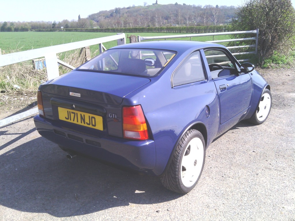 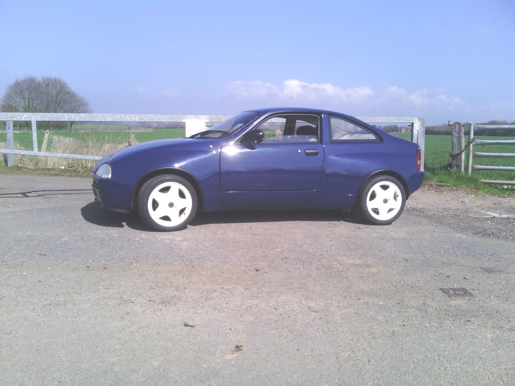 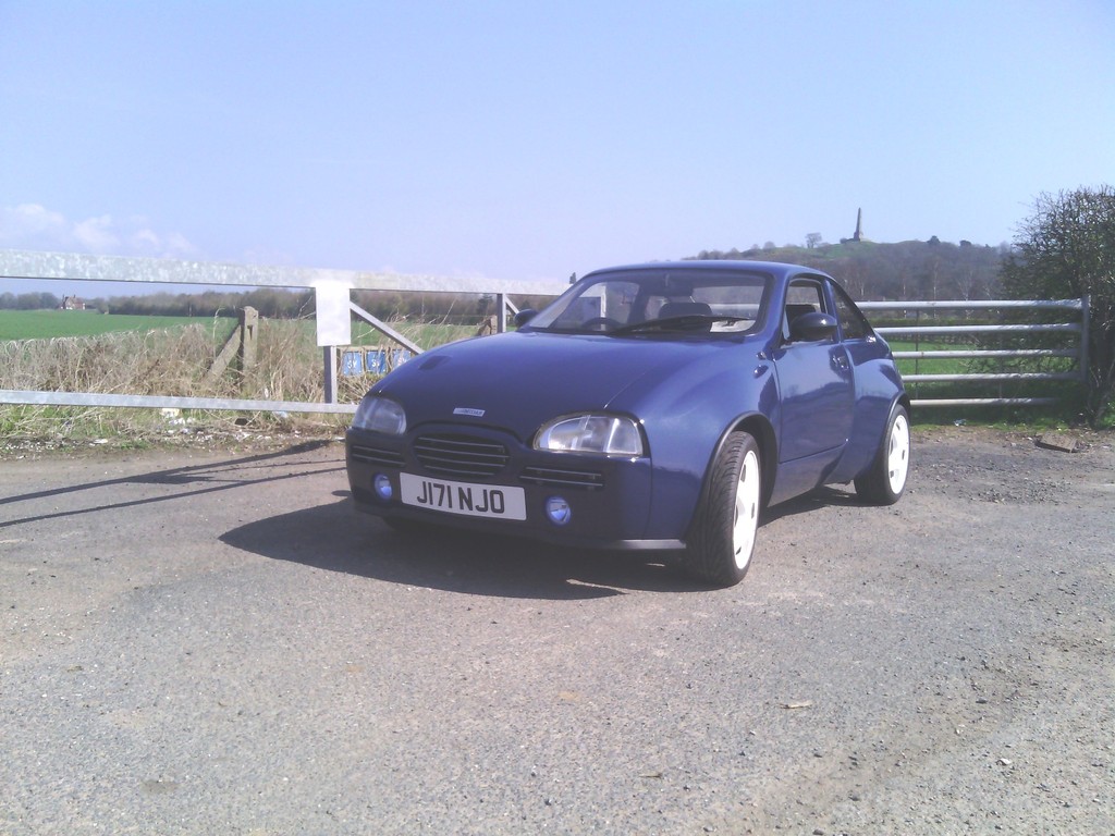 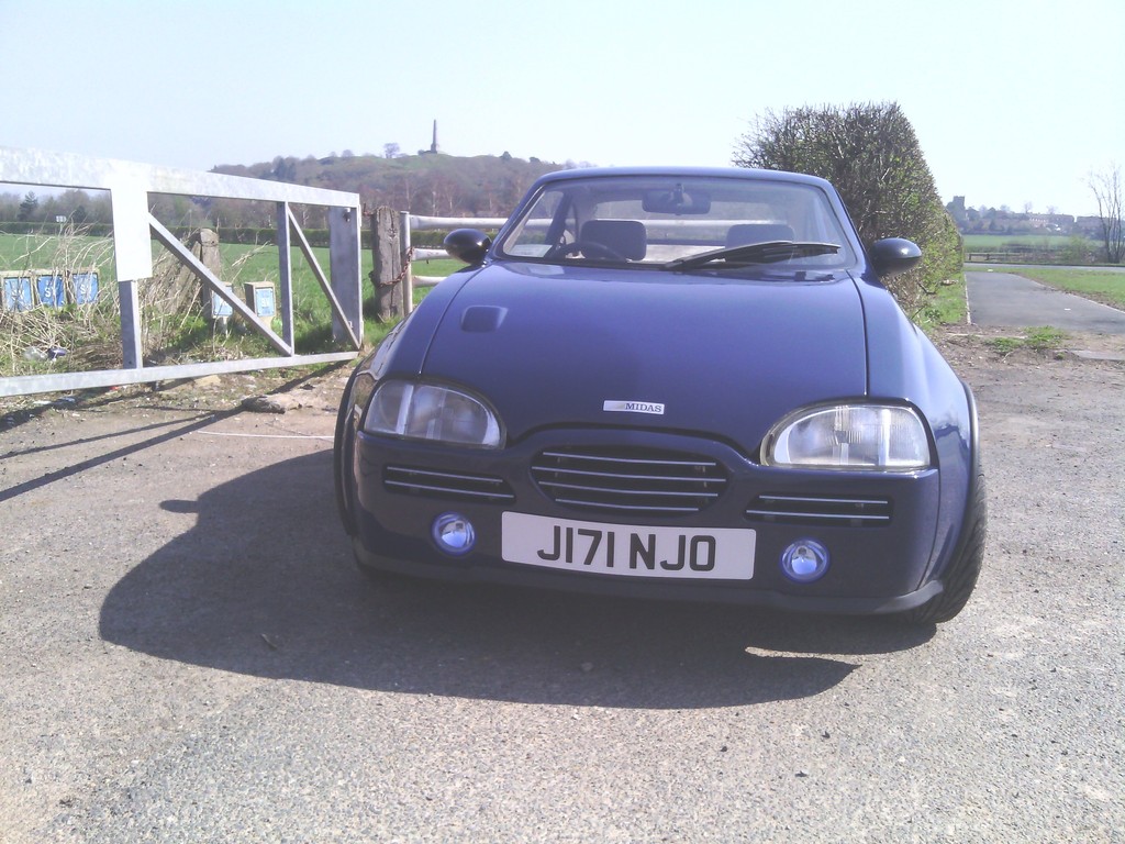 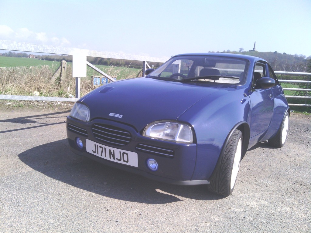 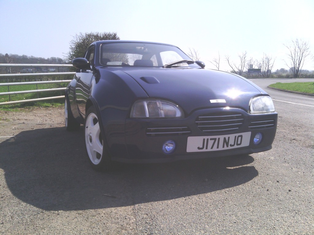 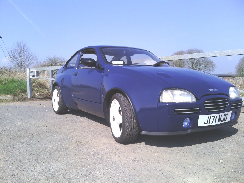 Also decided to upgrade the dim yellow number plate light bulbs for high power LEDs 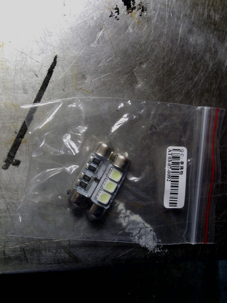   Best 99p I've ever spent | ||
| Jin |
| ||
| Regular Posts: 159    | june 2015 Bonnet vents I decided some time ago that I wanted to fit bonnet vents, and at Stoneleigh it looked like everyone else but me had them, so feeling a little under dressed I set about searching for the type I wanted. After a fair while it looked like the vent of my dreams didn’t exist , not helped by me not being a fan of swapping car parts between makes, I really don’t like seeing obvious ford vents on a fiat etc. I even bought a chance universal pair off ebay that were cheap and shonky and they turned out to be cheap and shonky , 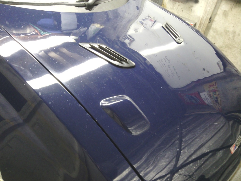 Then I started looking into the less obvious places and came across the rover 100 interior fan vents while looking for something else (always the way). These also satisfied my desire to keep the external styling within the same manufacturer - bonus Quick look on ebay for some cars being broken (no longer available new) I got a few pairs, 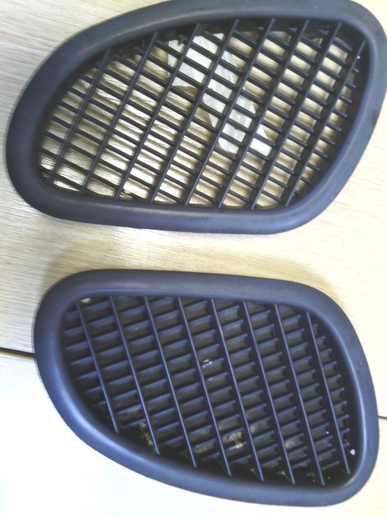 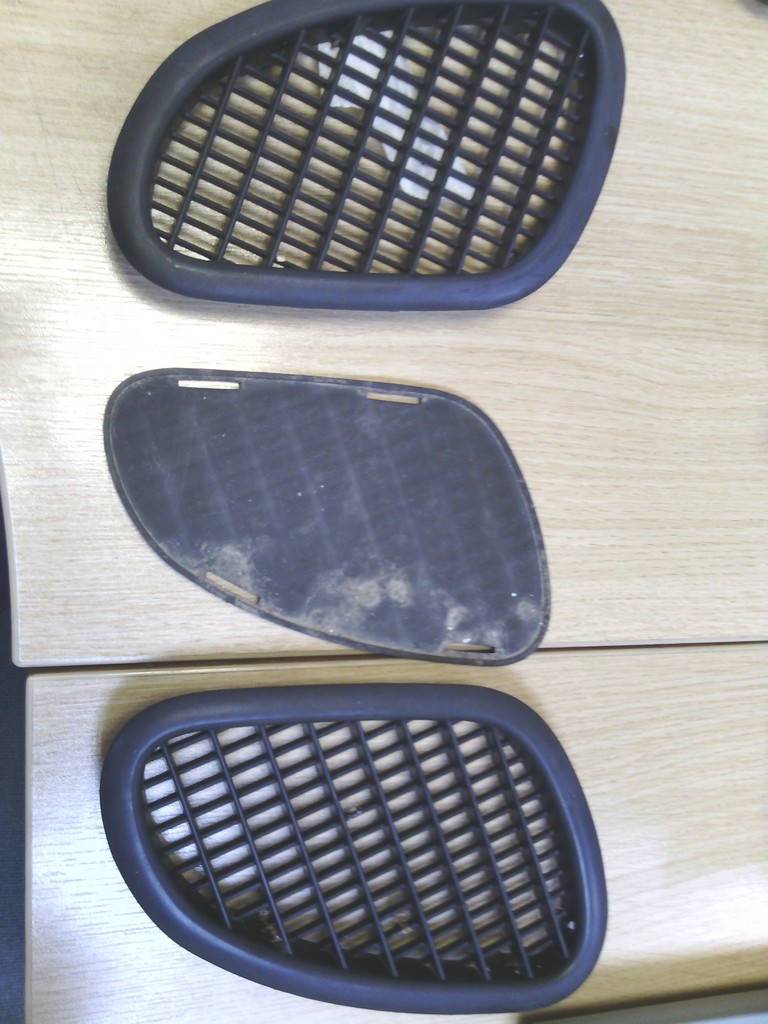 However after a quick clean up I realised that the outer flange isn’t flat and flush to the body like I initially thought 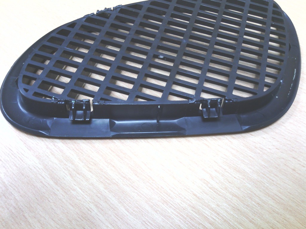 - bummer, however I had decided to go with these and I liked the initial look loads so I pondered it for a while before bonding on some predetermined thickness washers to a file that were the same thickness as the lower part of the flange with the vent upturned, then with it all sat on a flat plate I filed the outer edge flat and smooth level with its lower recess, now once installed the vents would sit nice and flush to the bonnet, that may sound easy but in reality filing all that plastic while holding the file with just your fingertips is a bit like torture. 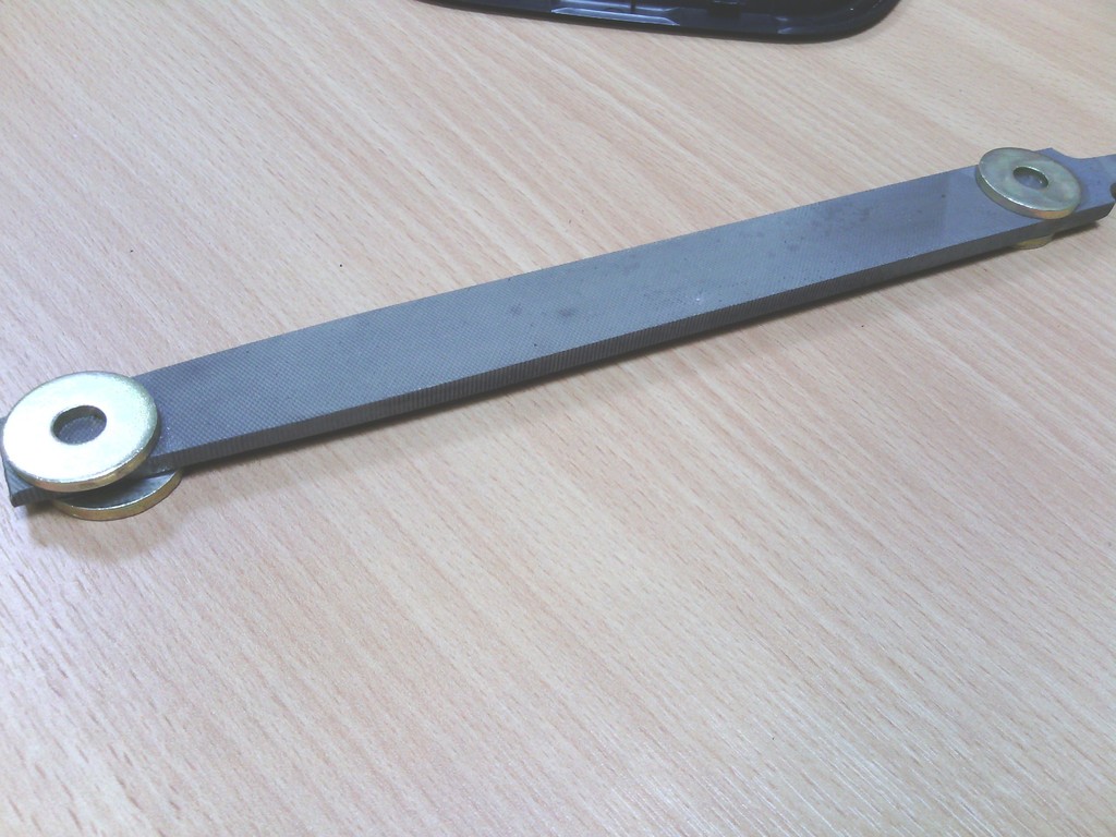 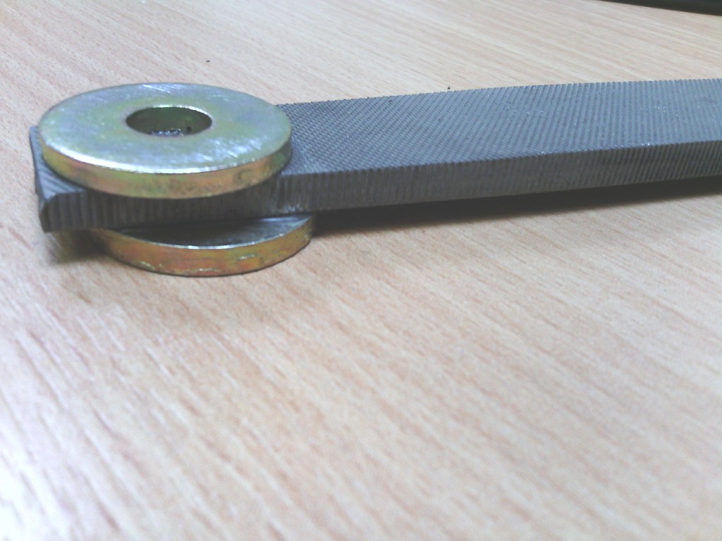 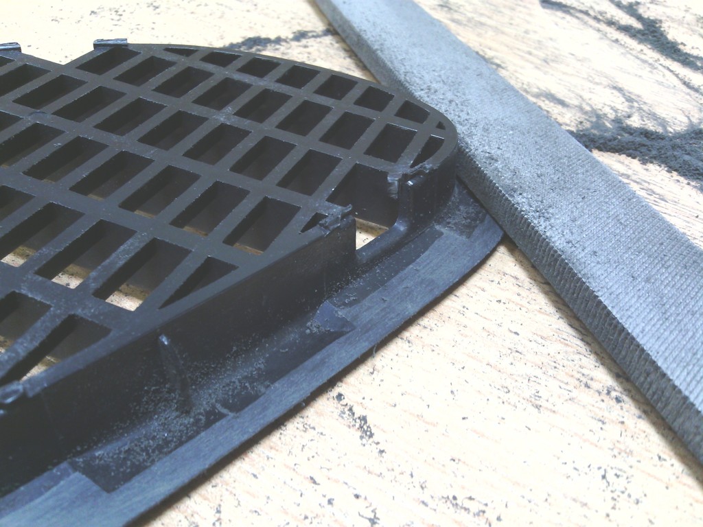 Those done I set about finding the locations right, it wasn’t so much a case of finding where they would have to go to avoid various fixings on the bonnet or the engine below, but more a way to find out where they looked their best and how much of a pain in the arse it would be to make it work, after trying many many orientations on the bonnet I eventually dropped into the winning location (in my opinion) this was nothing to do with heat or aerodynamics – purely cosmetic and what made me smile. 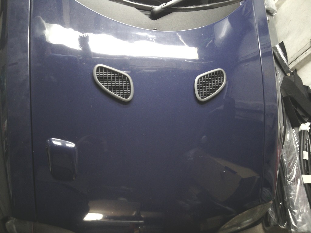 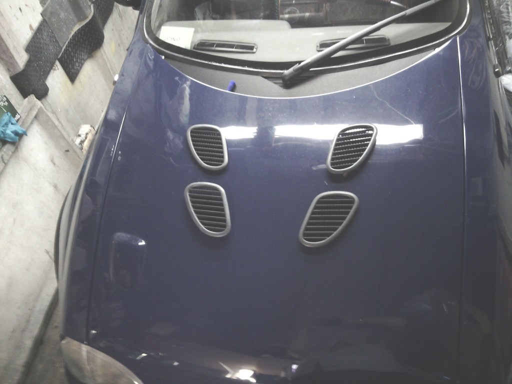 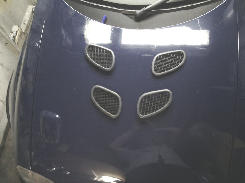 A quick draw around to get the location was done then this was transferred to a piece of A3 paper and cut out, then using the flat side of the paper as a datum against the flat edge of the bonnet sides and a single set distance from the scuttle for example – the whole piece could be flipped over to the other side to mirror the exact location there so to keep them in the same location and orientation – nothing worse than wonky bonnet vents. 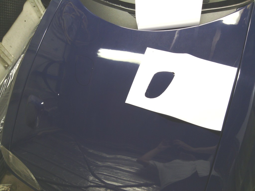 I then used a similar method to find out what was going to cause me a headache on the underside by taping the template back on to the wing this time and opening the bonnet. 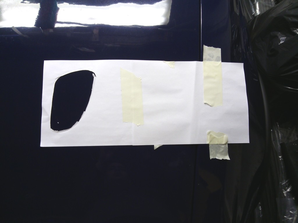 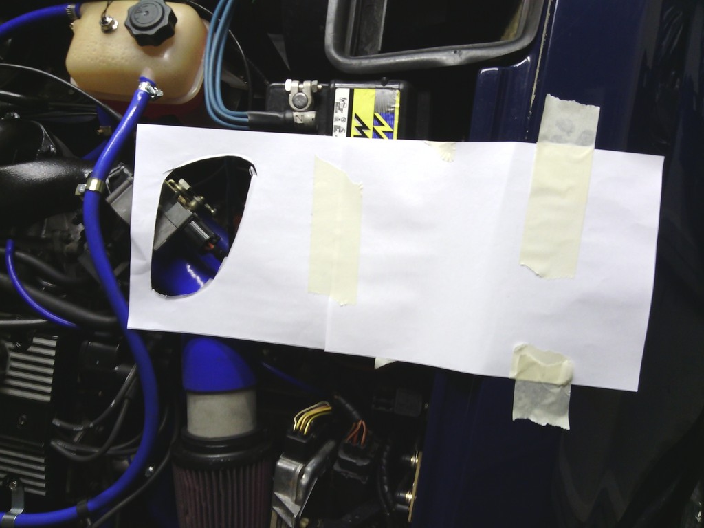 It didn’t look too bad, there was nothing immovable in my way such as the top of the engine rubbing on the bonnet underside, but it was hardly ideal since it was right over the injector wiring and throttle body, ill sort that later. Once the final position was marked out I carefully drilled the 4 pilot holes to allow saw access, 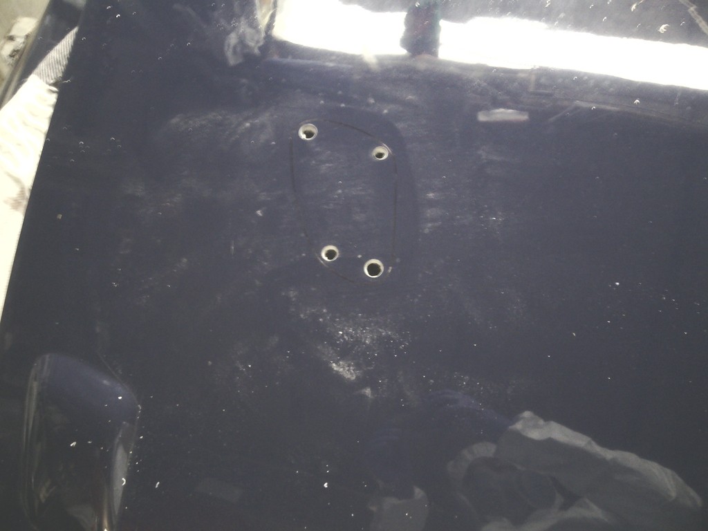 No going back then Then I carefully and gently cut into the bonnet with a 18tpi hacksaw blade by hand. It soon became apparent I was going to do more damage this was by slipping with the blade twice and scuffing the bonnet with the first inch of cut so I taped over the foot of my jigsaw to protect the paint and very quickly hacked it to pieces, thankfully in roughly the right shape. 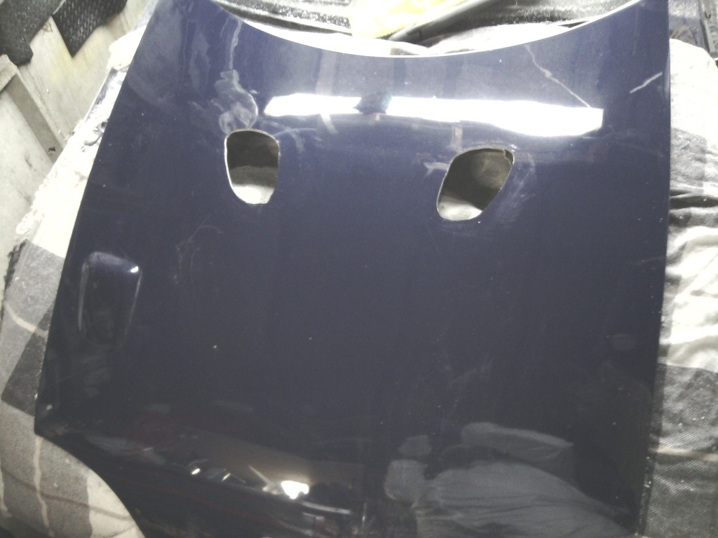 A quick tidy up with a flap wheel and the holes were perfect for my needs, thankfully the bonnet is relatively flat here so minimal bending of the vents is needed. With both vents tapped into place with a couple of miles of gaffa tape and wooden blocks to keep them pressed flat to the bonnet, I spot glued them into place from behind with lotite 409 superglue gel, and left over night. 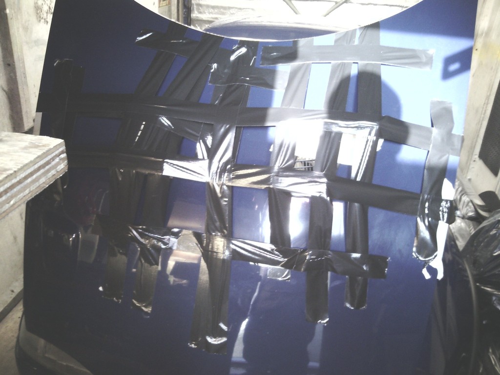 upon removal of the tape in the morning I was rather happy with the results 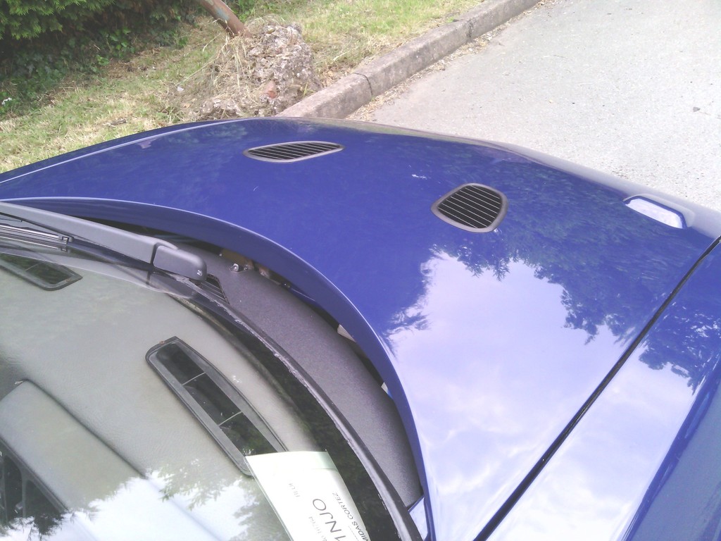 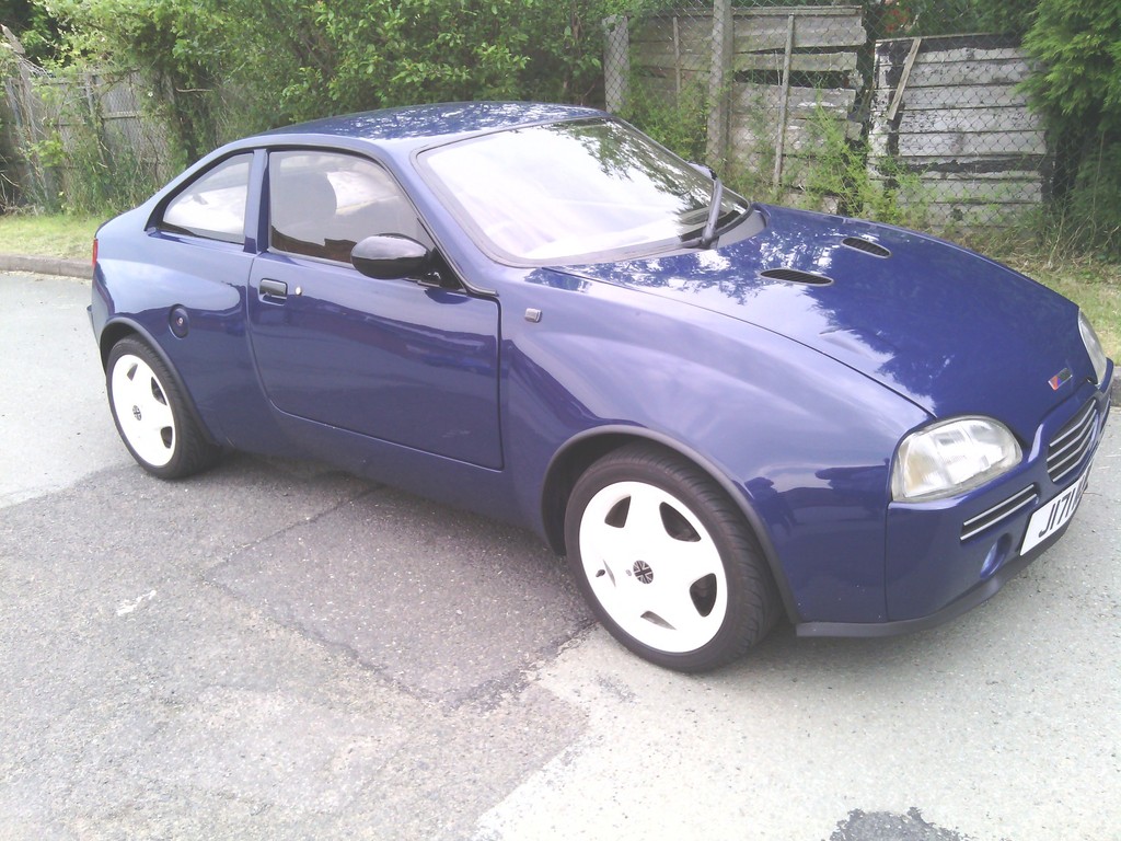 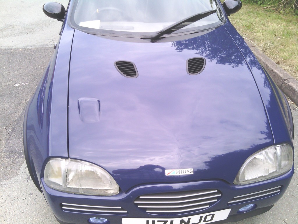 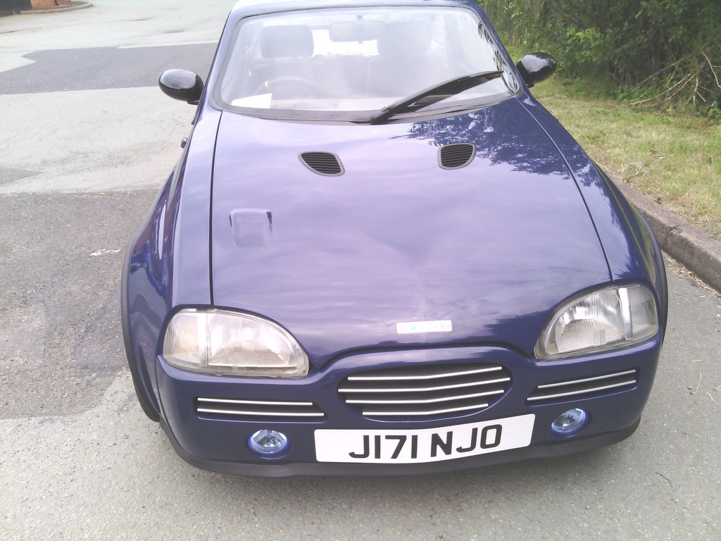 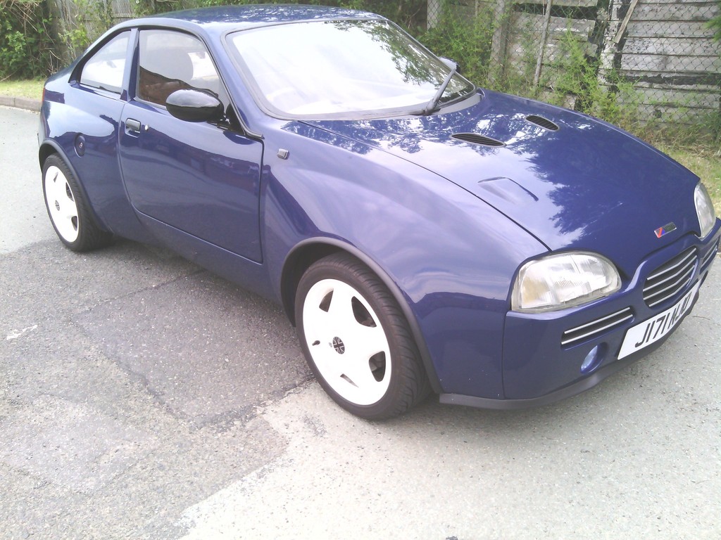 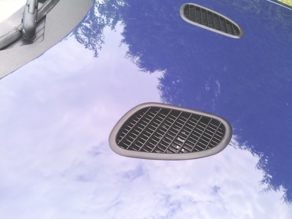 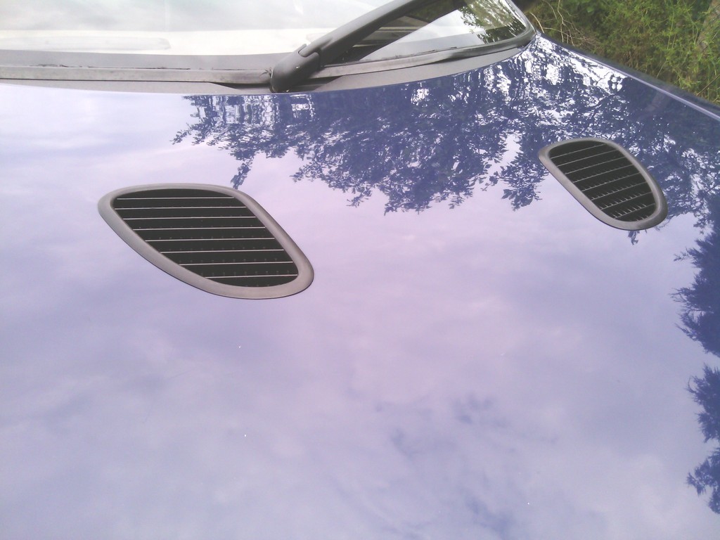 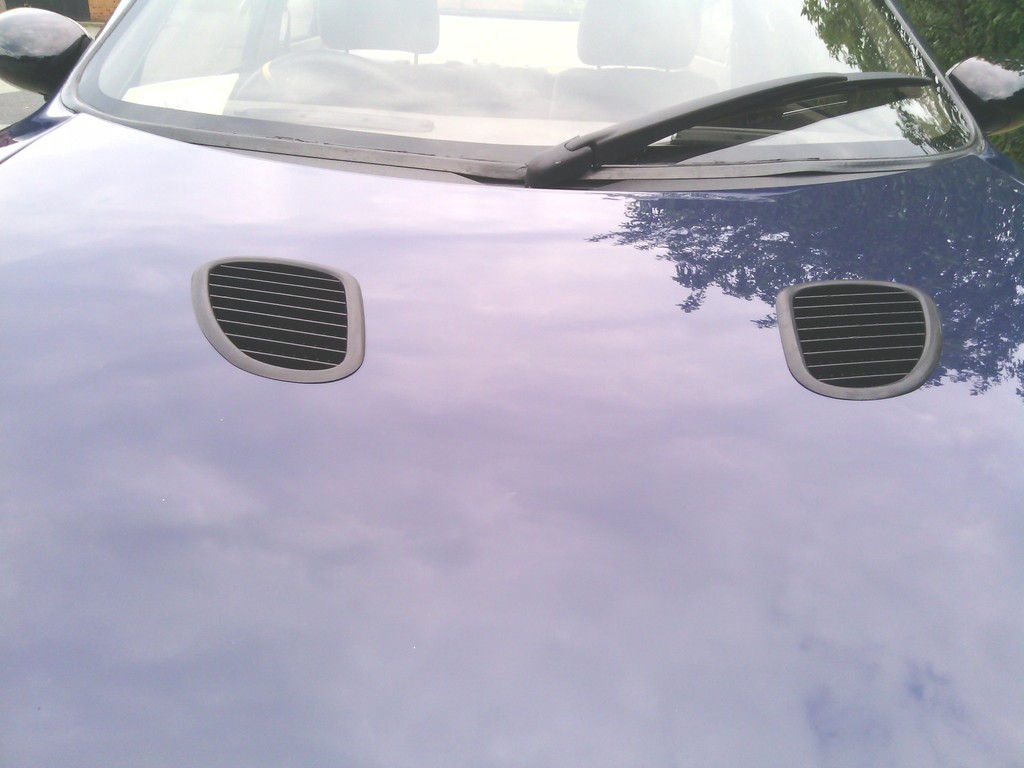 Last job to do is make 2 water trays to channel water away from the various components you don’t want getting wet, but to liven up an otherwise plain bonnet it’s not come out too bad and gives the car a more aggressive touch to the front. Next up – custom boot spoiler… | ||
| Jin |
| ||
| Regular Posts: 159    | JULY 2015 More carpeting While taking my time to do the front foot wells I jumped on the chance to sort the parcel shelf, its current state was terrible 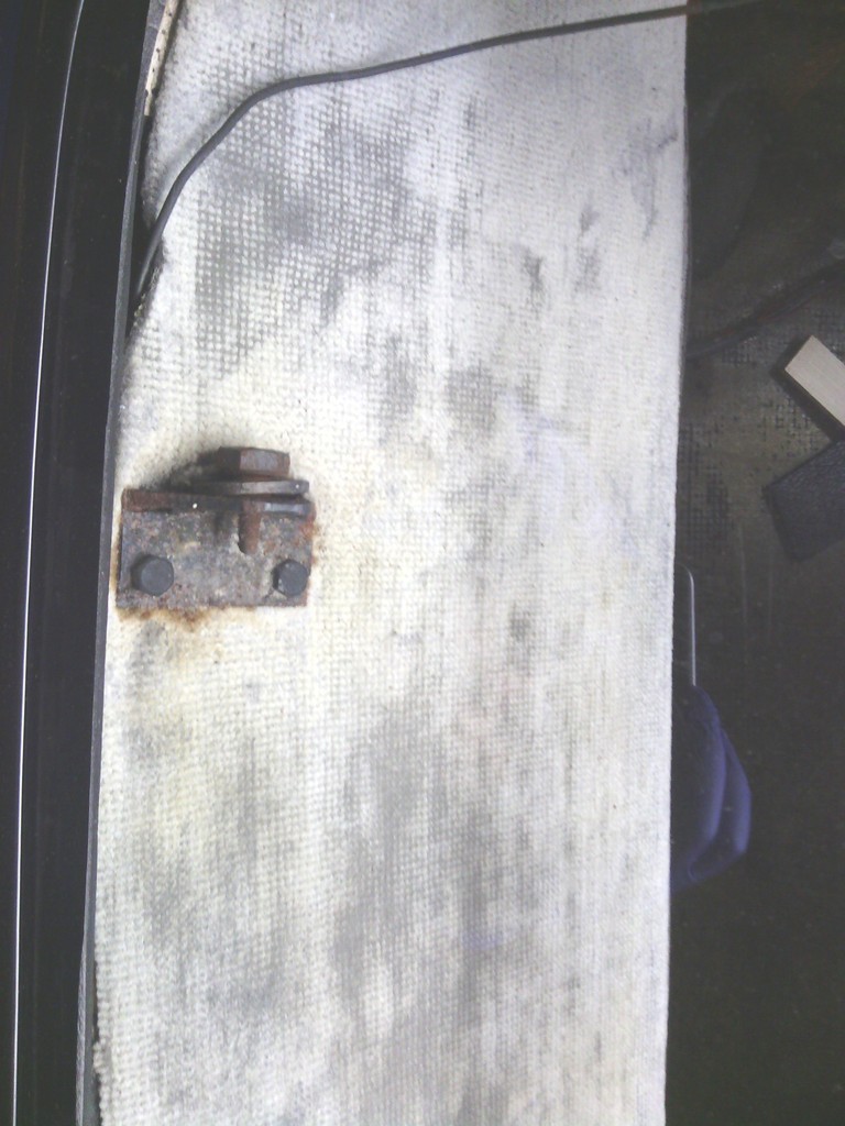 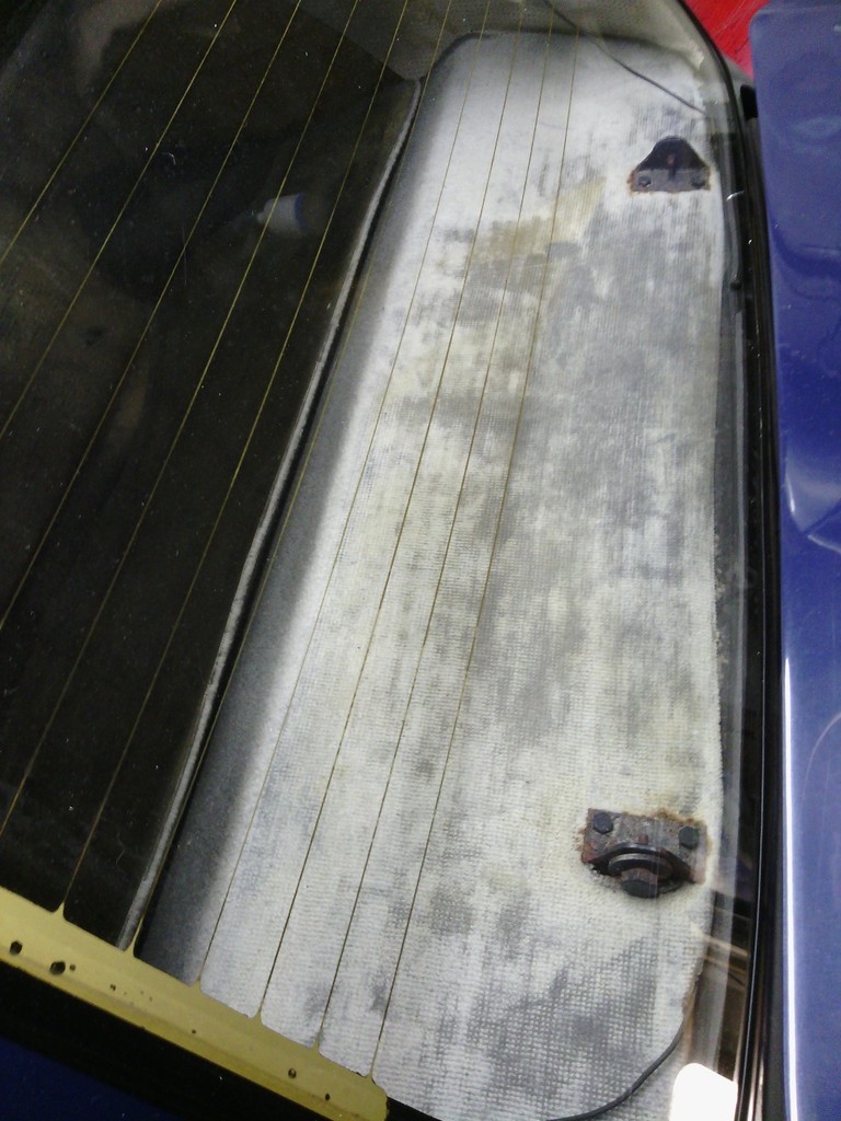 So without a moment to loose I whipped off the rusty boot hinges and blasted them 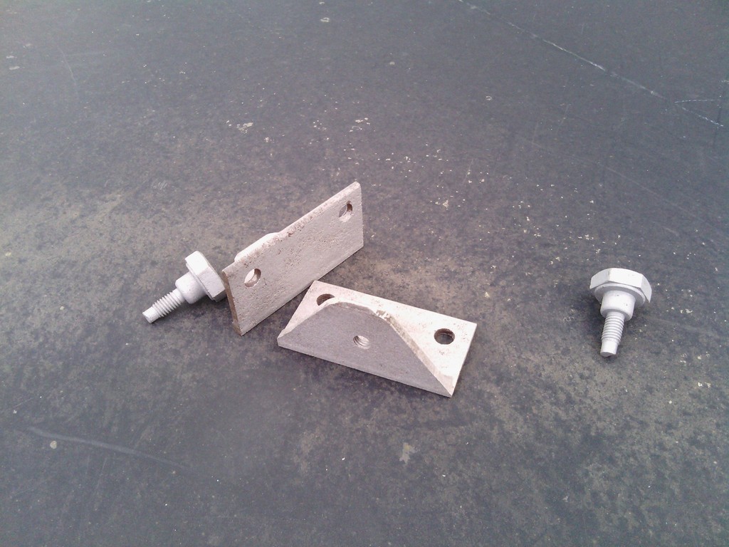 Quick coat of paint 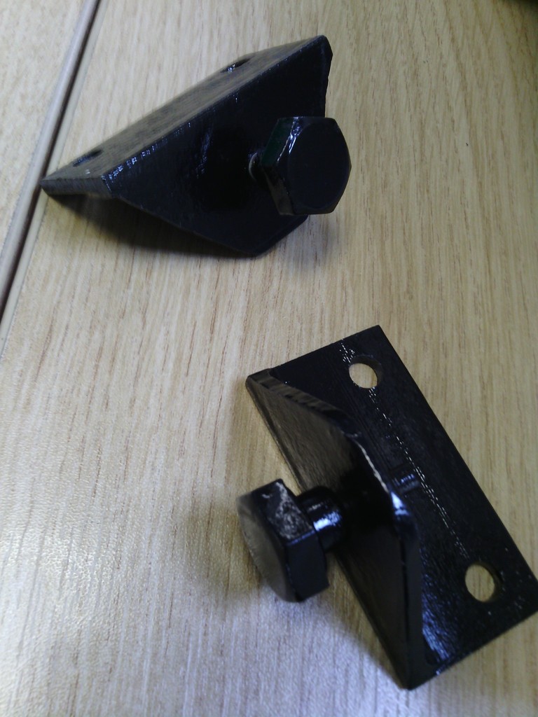 With the boot lid removed now seemed like a good time to trim down the rear return edge of the boot lid since it caught the rear bulkhead below the screen each time it was opened and that’s with the boot lid set out of line in an attempt by the builder presumably to avoid the issue, in total around 10mm was trimmed off 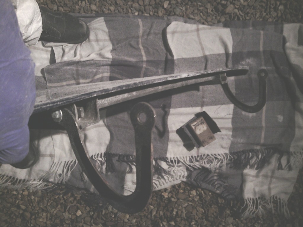 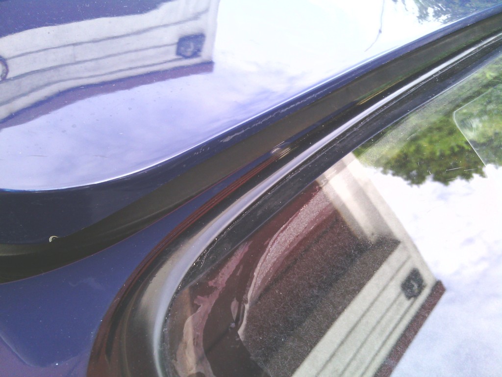 Worth it though, now the boot lid could be realigned to perfection 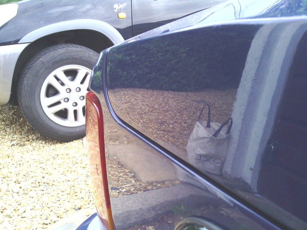 Hinges reinstalled and a mod standoff made to cover them up after 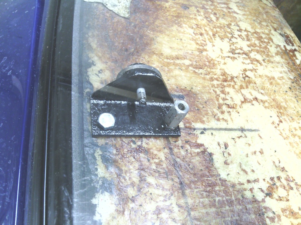 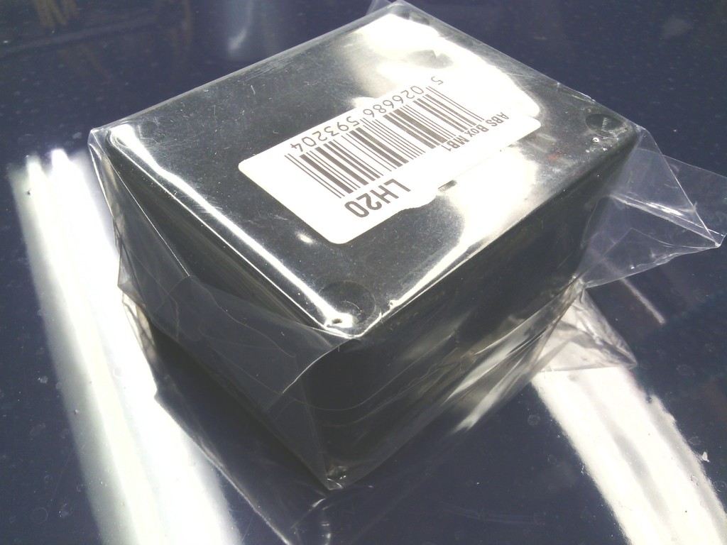 Bought some black plastic project boxes from Maplin, quick trim down and hole drilled and all is good 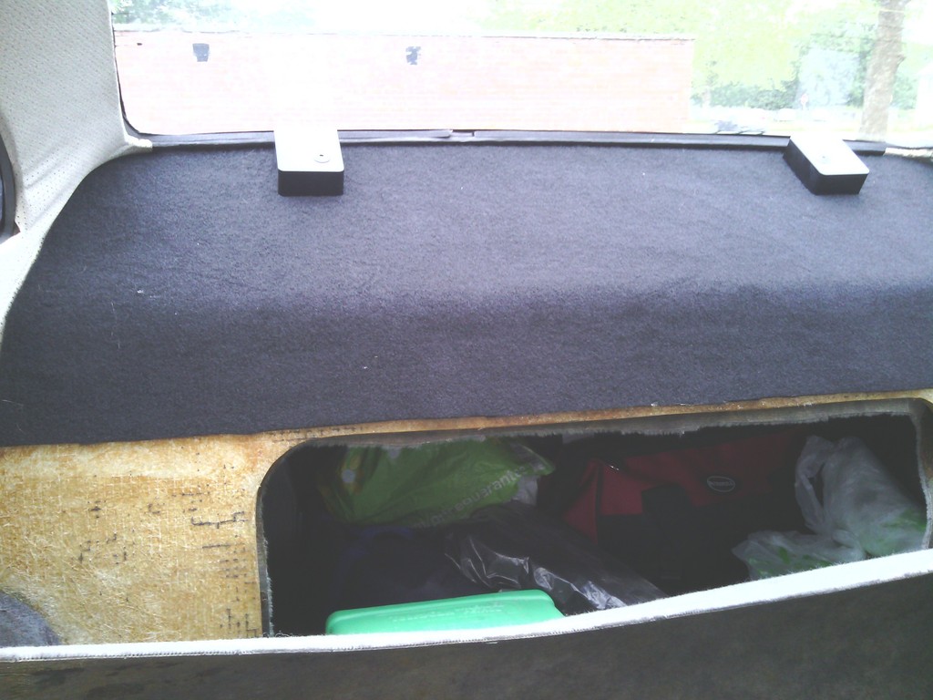 Much nicer though I may carpet the hinge covers too Onto the foot wells The sound deadening was trimmed to fit snug 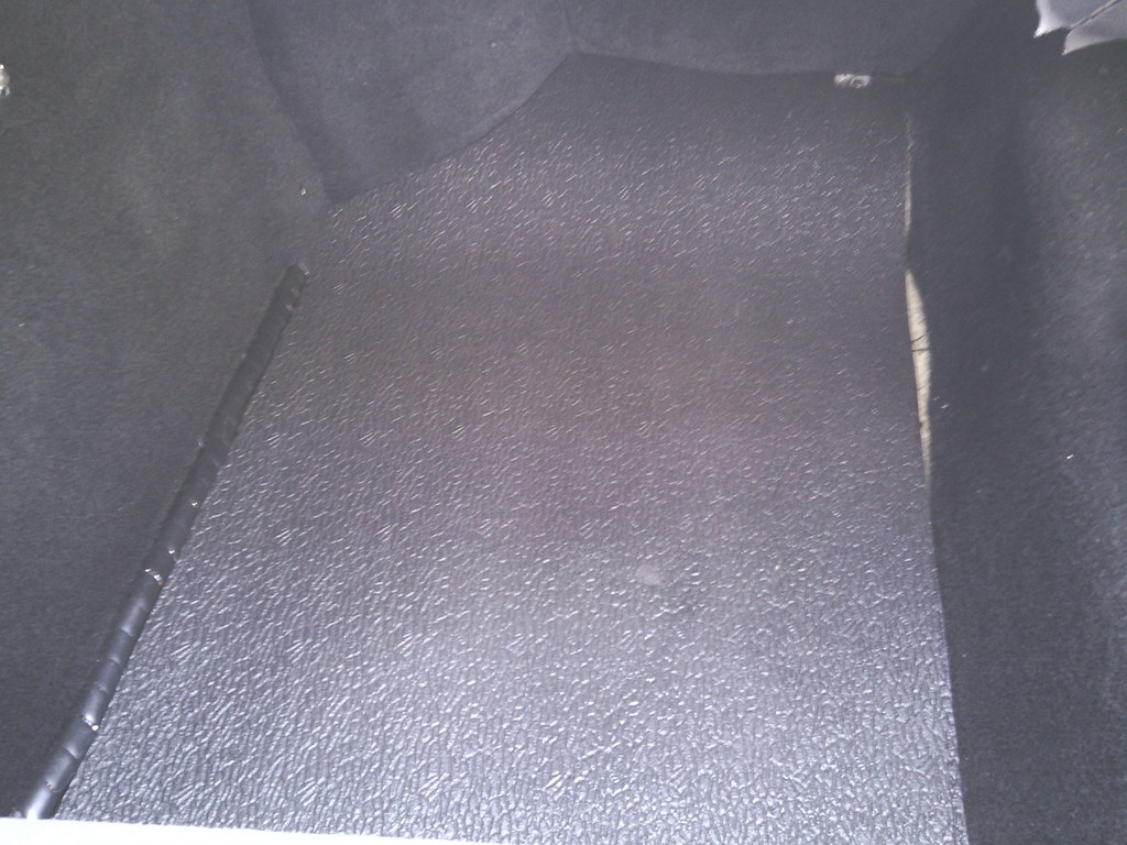 Carpet trimmed to fit in exactly butting up tight to the surrounding carpet, this way the joins are virtually invisible but the cutting has to be mm accurate, fortunately I managed it 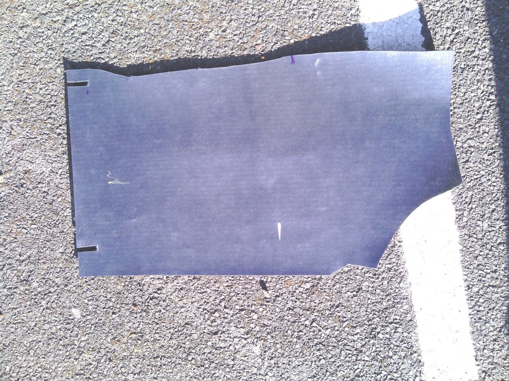 Sound deadening shown for comparison 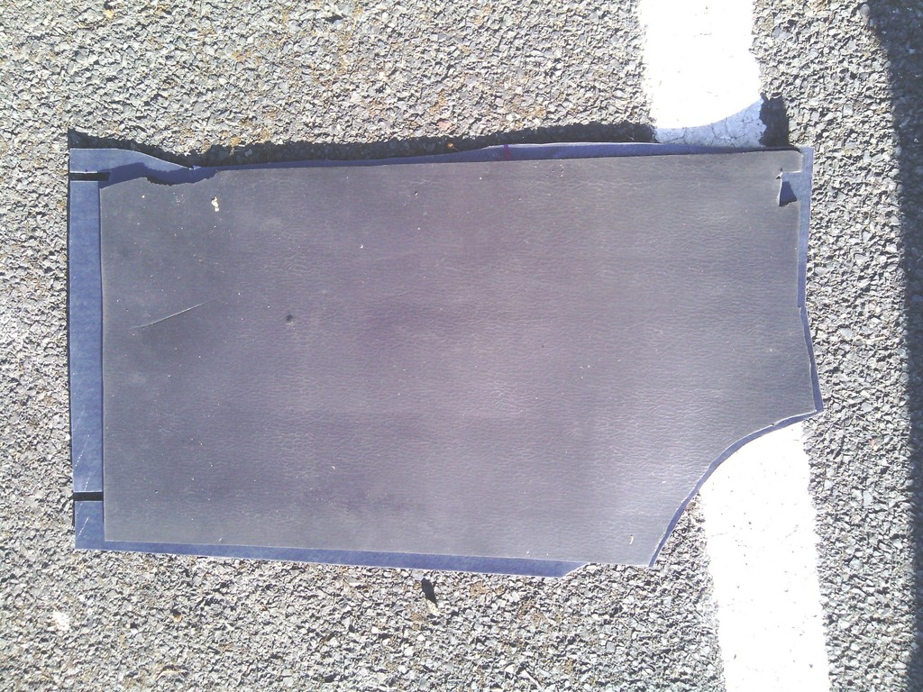 Dropped in and the fit is snug 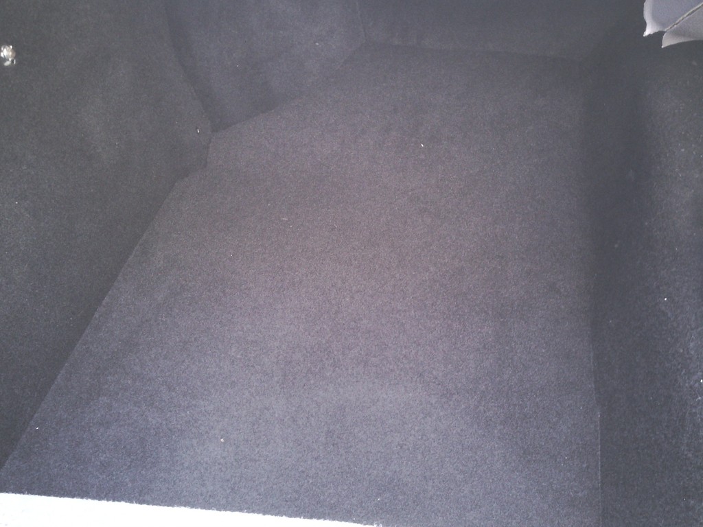 Trouble is this is just going to slide around all over the place and I don’t intend to bond them to the floor since ill need to access the sub frame nuts etc. and need to mop up any leaks should they occur, so I bought some 10mm polycarbonate sheet which happened to be the exact thickness of the sound deadening 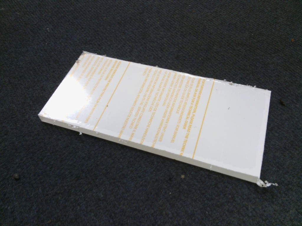 Cut it up to 2” circles 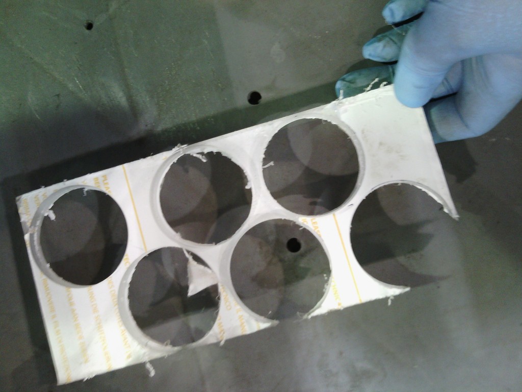 Got my money’s worth out of that 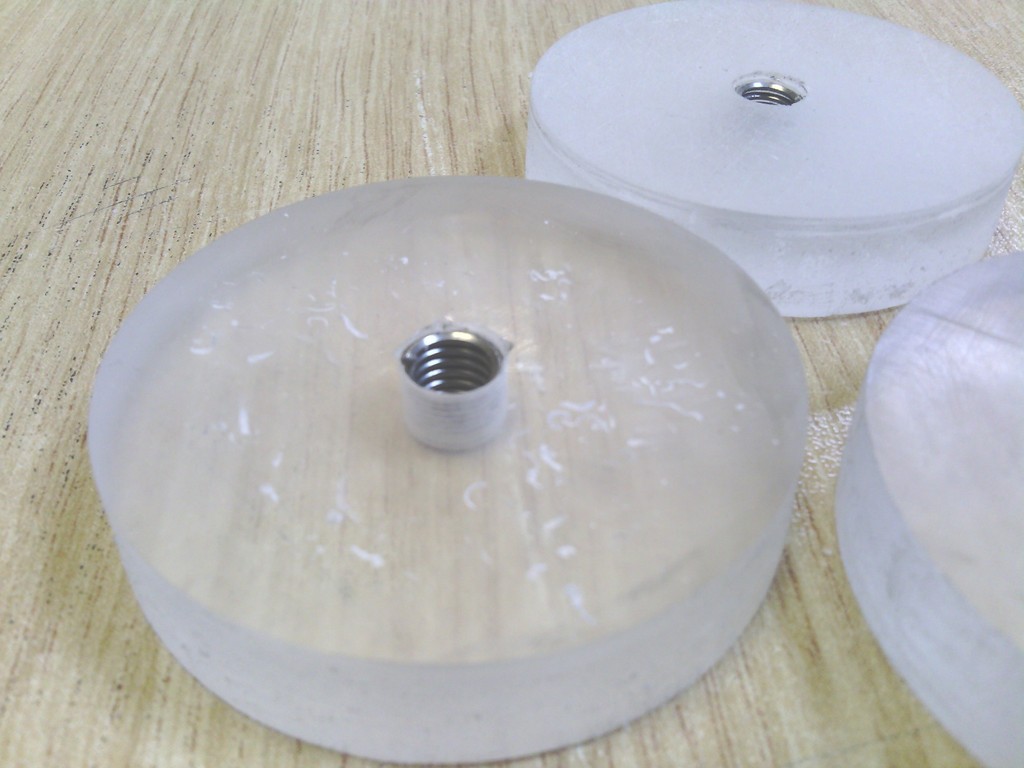 M6 stainless inserts 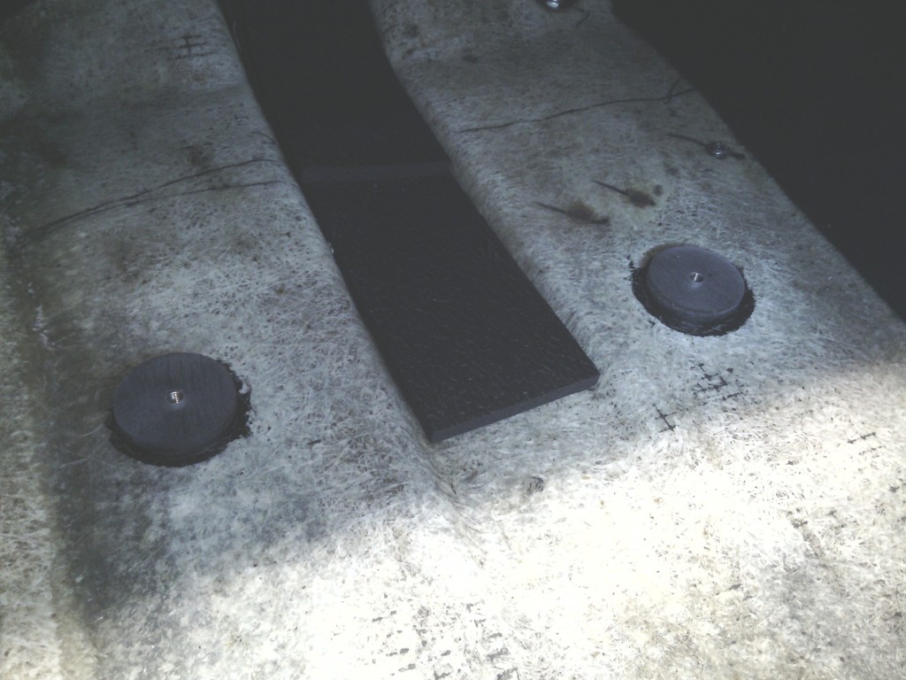 Bonded to the floor With corresponding holes punched into the sound deadening 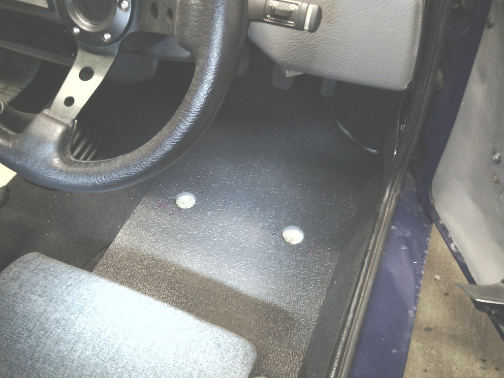 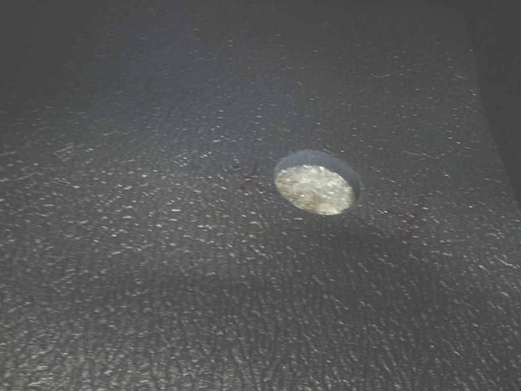 Perfect fit 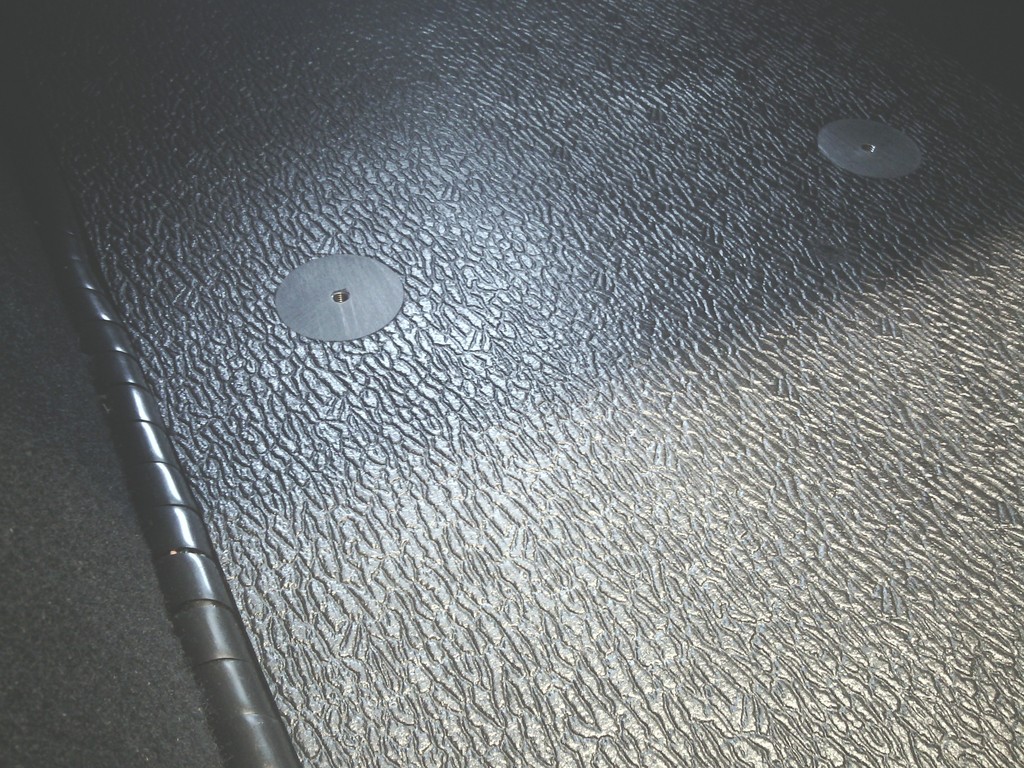 Then step 2 was to bond the carpet to this 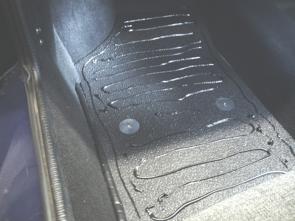 Then once set I whipped them out and sealed all-round the edges with polyurethane to make them one semi ridged removable waterproof floor section, Then the last job was to punch out a 6mm hole that lined up with the threaded inserts in the floor locaters and some black flat alloy screws used to nip them down, no unwanted movement whatsoever and the screws will be hidden by some over mats 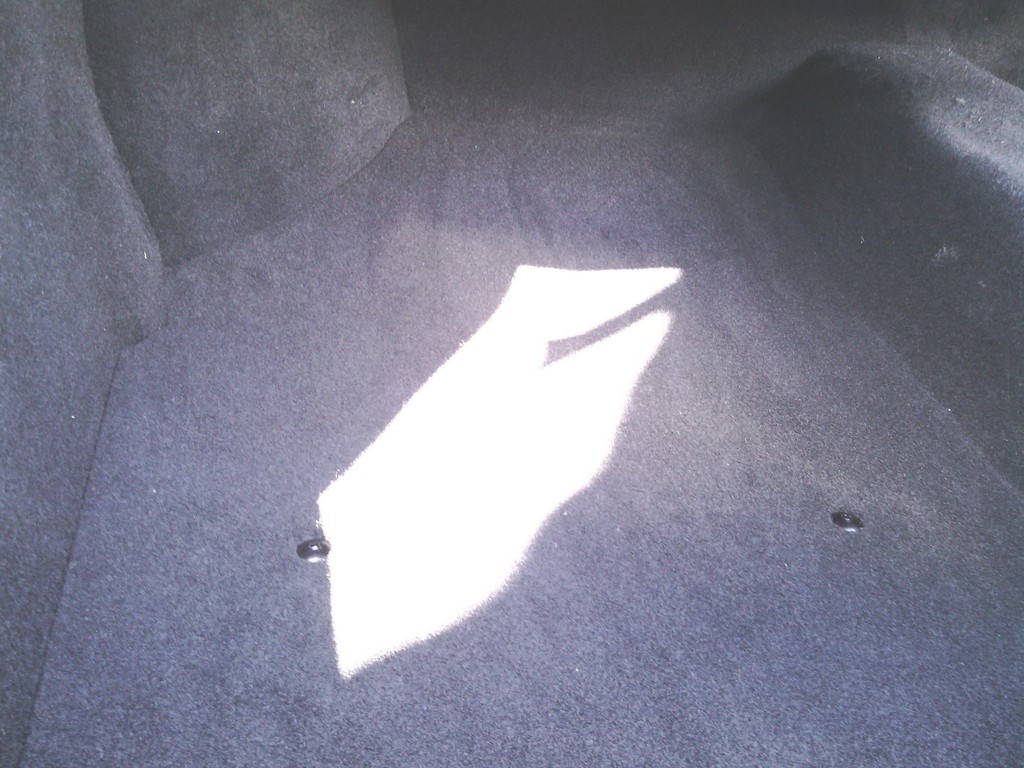 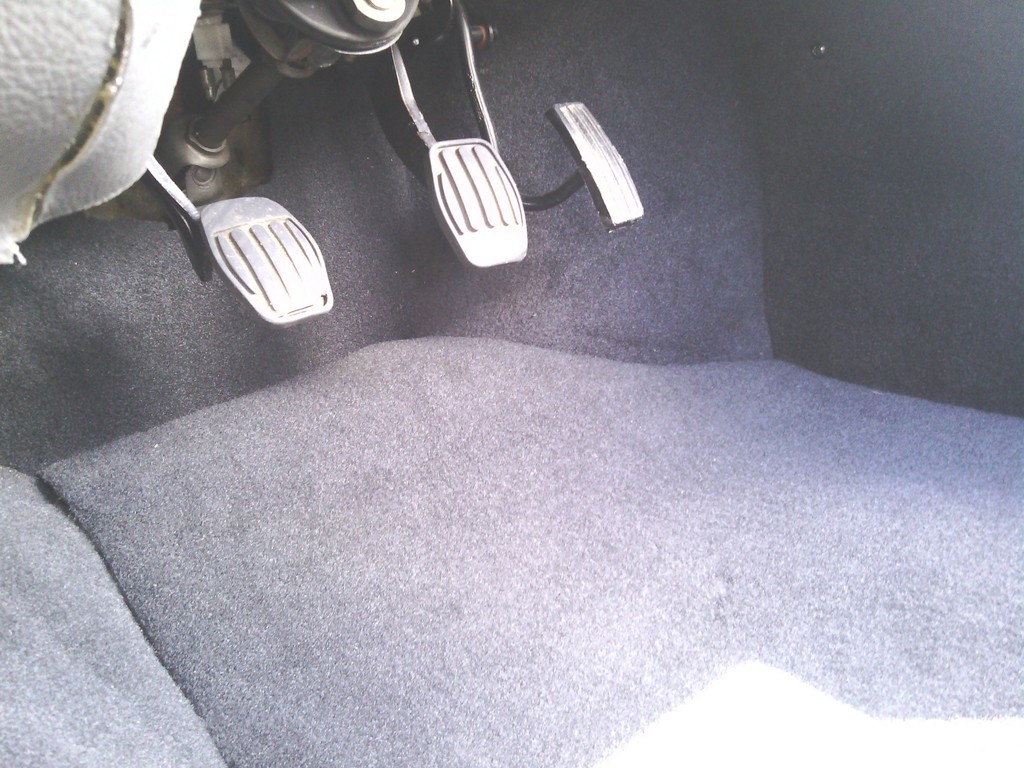 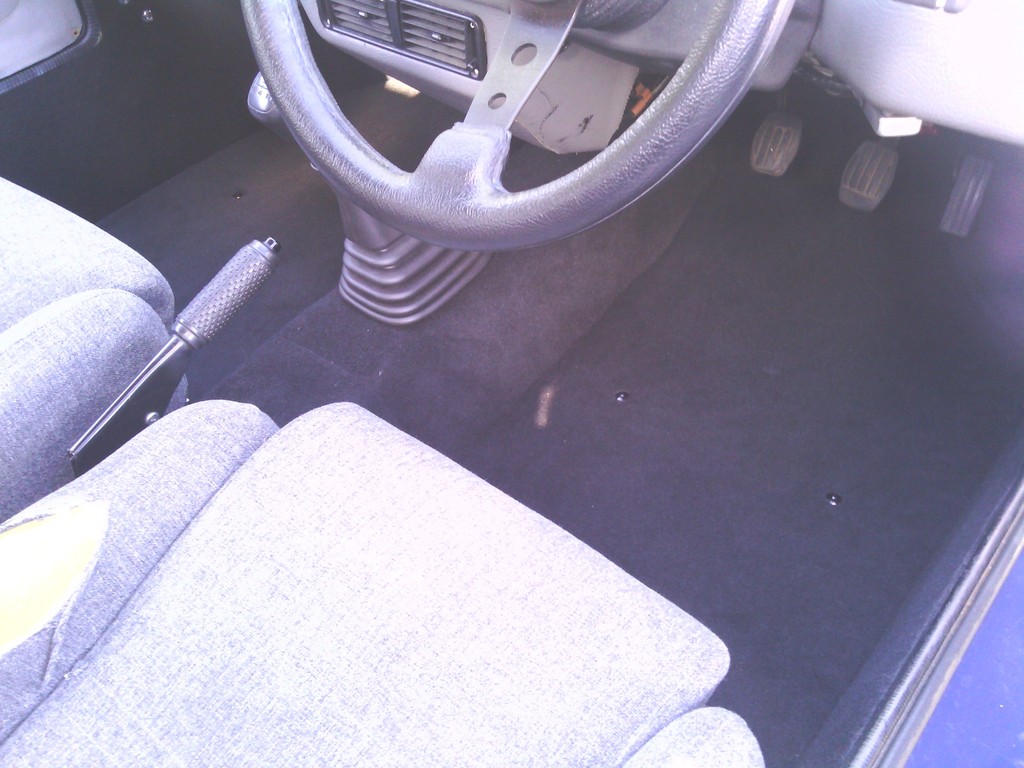 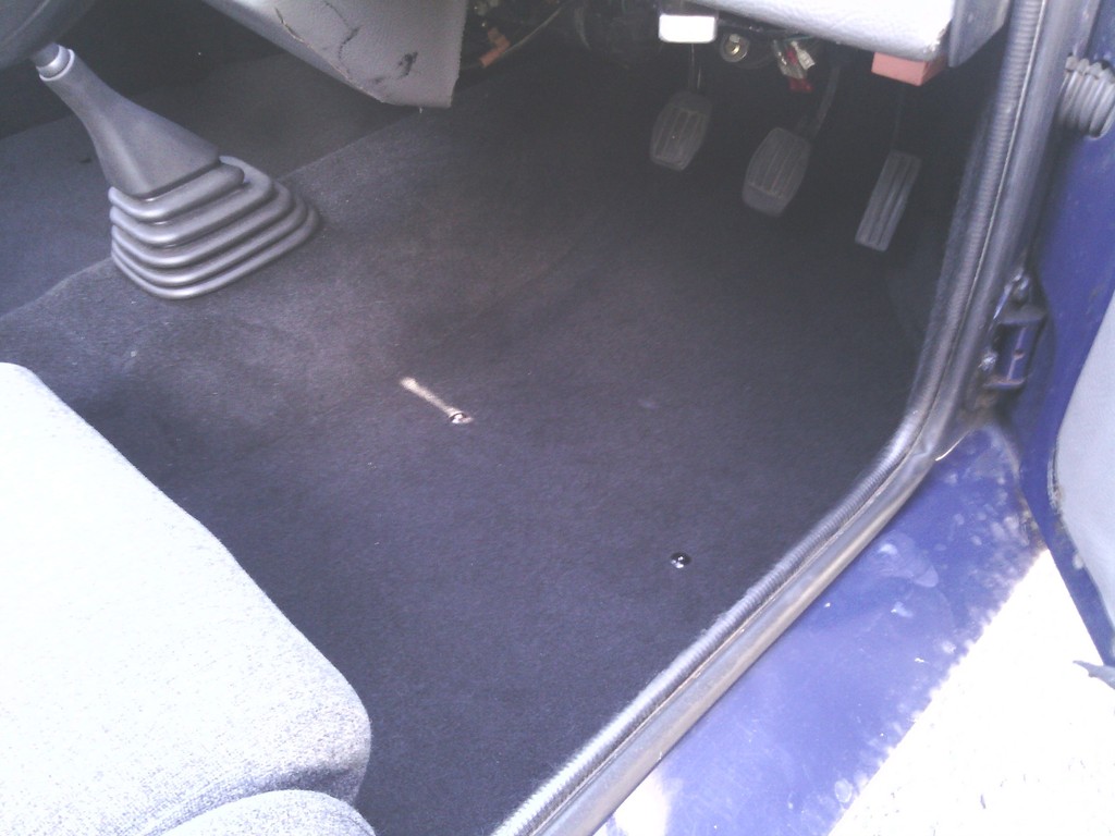 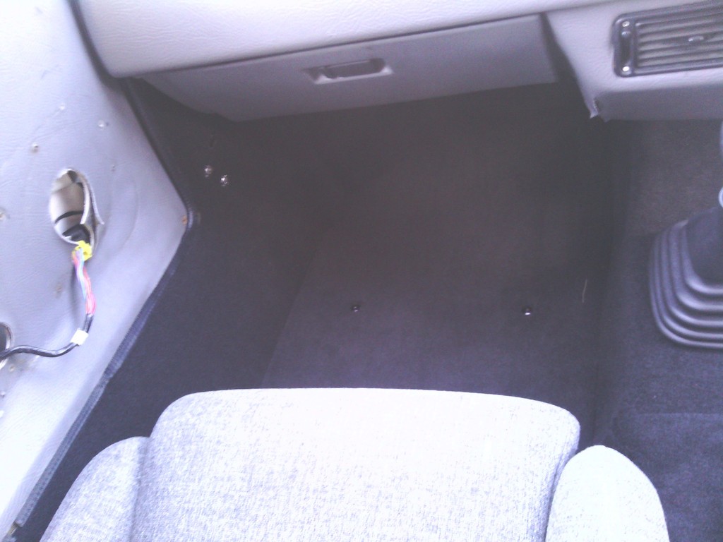 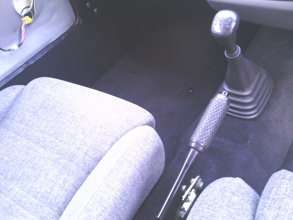 Work continues at the rear foot wells, the passenger side gave me a bit of a headache due to the fuel pump and main loom wiring running through this area, so I bonded some wood blokes to make a frame to support the carpet to the desired shape, I chose wood since ill need to access the wires from time to time so this section of the carpet can be secured with subtle black self-tappers 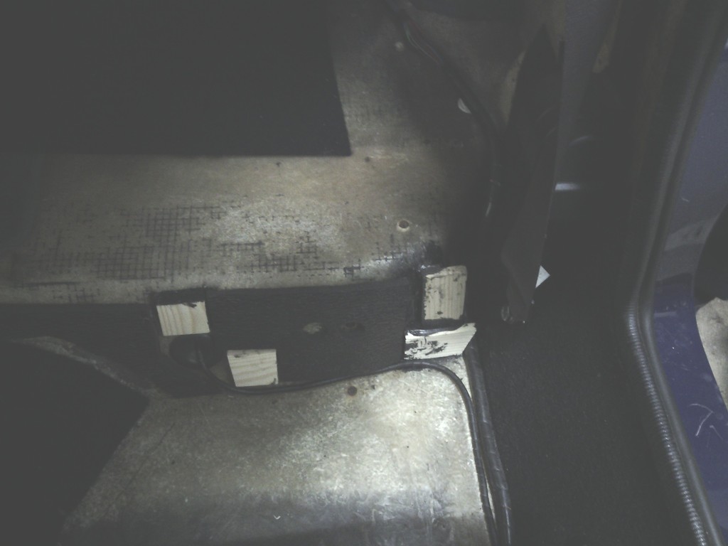 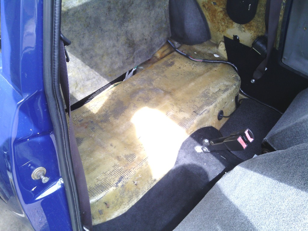 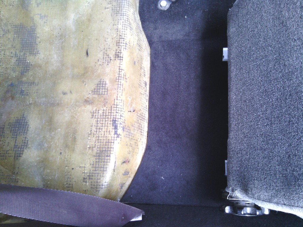 Also there needed to be access to the rear brake pipe clip screws from inside the rear foot wells, it seemed overkill to make the whole carpet removable and this carpet doesn’t sit flat too well either so it was bonded on with a lift up flap 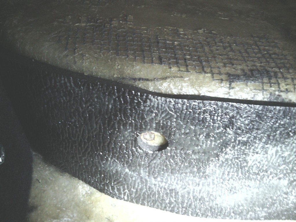 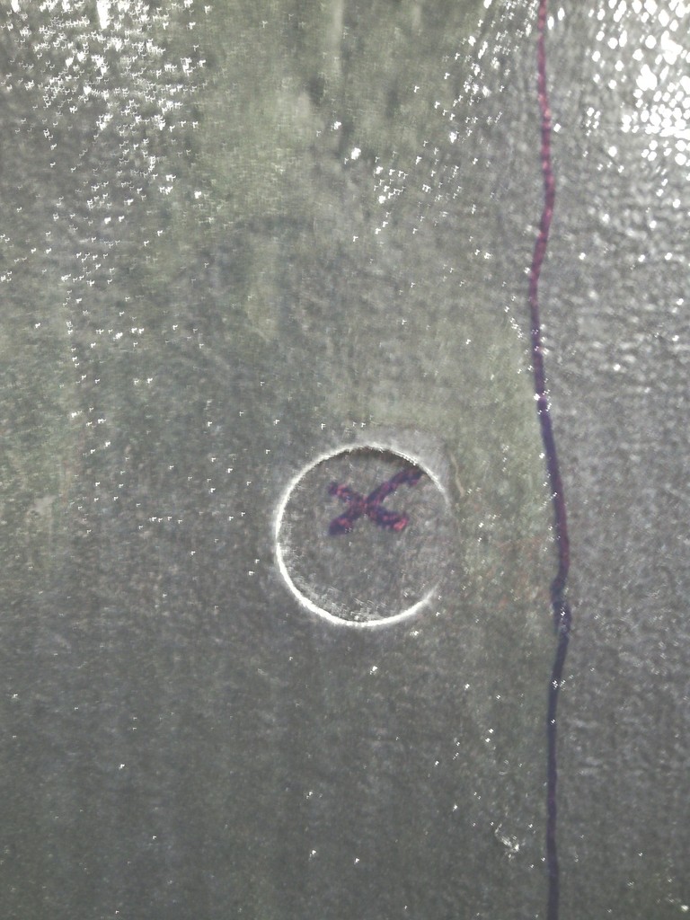 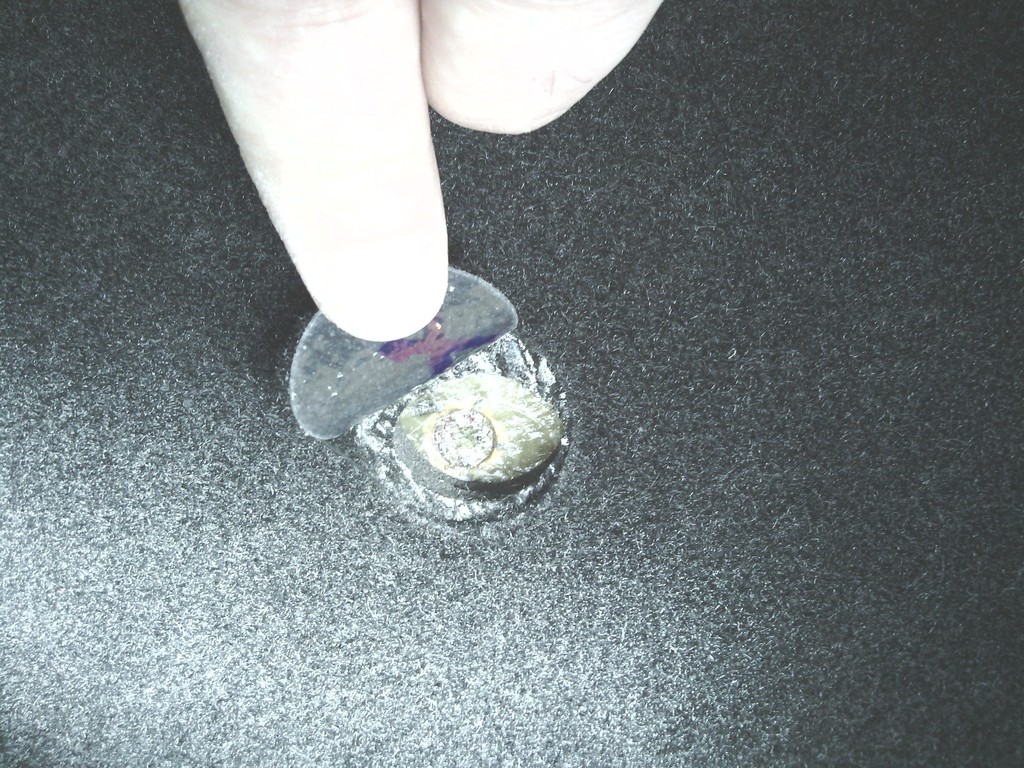  Rear floor sections being made in the same way as the fronts, new bucket seats on order so things are progressing nicely… Edited by Jin 12/11/2015 2:13 PM | ||
| Jin |
| ||
| Regular Posts: 159    | JULY 2015 even More carpeting Since I can’t do much on the car at the mo I thought I may as well write up what I have done to date. The rear floor mats have been made the same as the fronts by bonding to the sound deadening to form one single mat 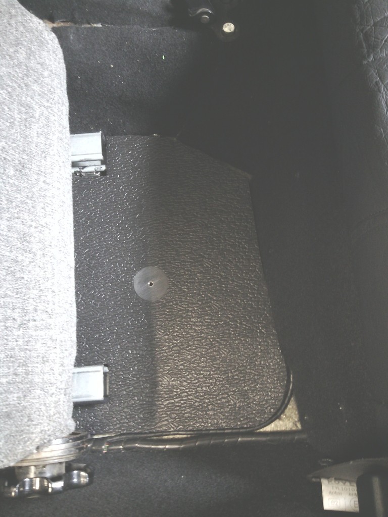 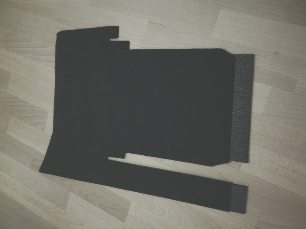 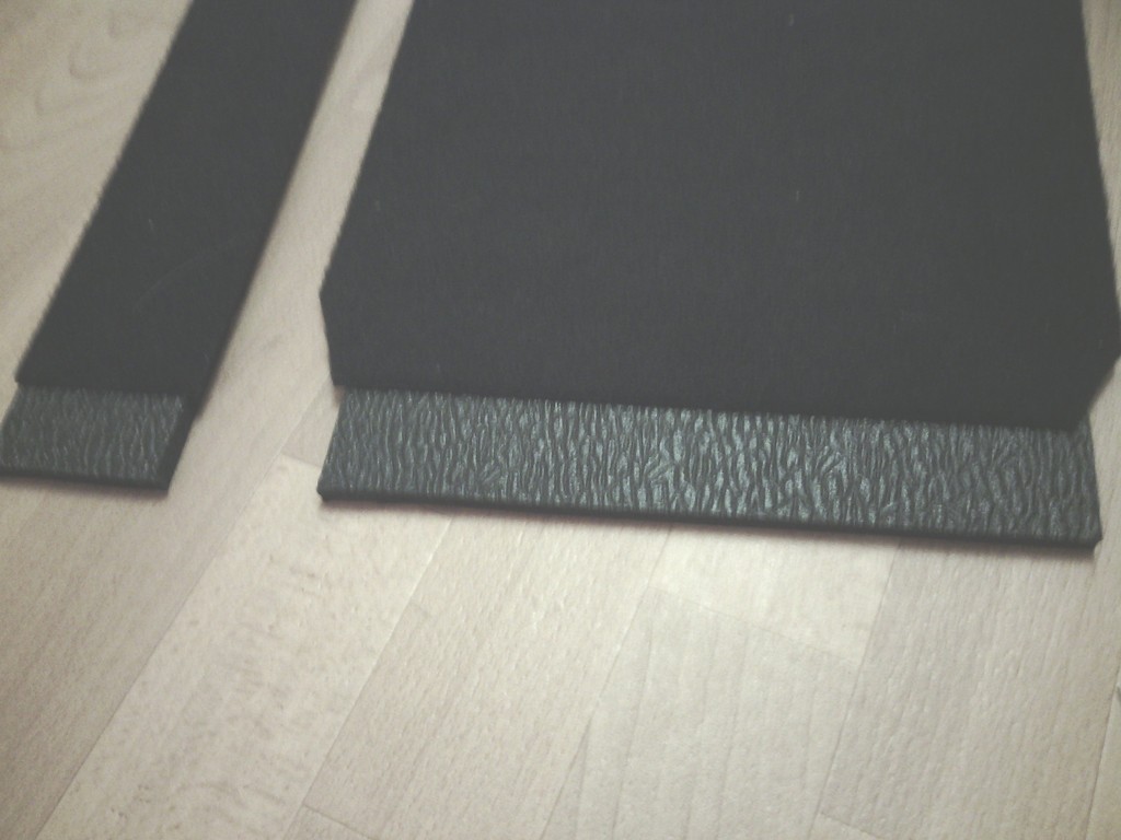 The step at the front of the rear mat (bottom of pic) locates exactly into the corresponding step at the rear of the front mats 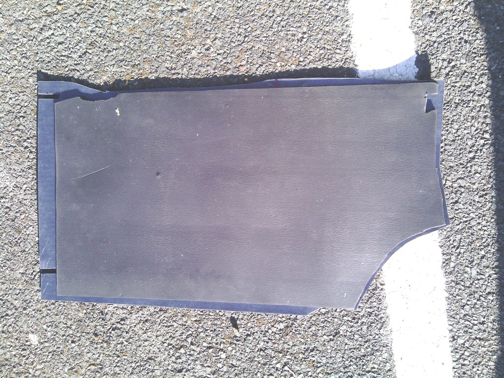 Left of pic So when the 2 are secured into the car they interlock so there is no visible join, and even if there was a slight movement of the mats the floor of the car would still be hidden due to the overlap, part of the join is shown here below perpendicular to the seat runner but as intended can barely be seen due to the tight dimensions 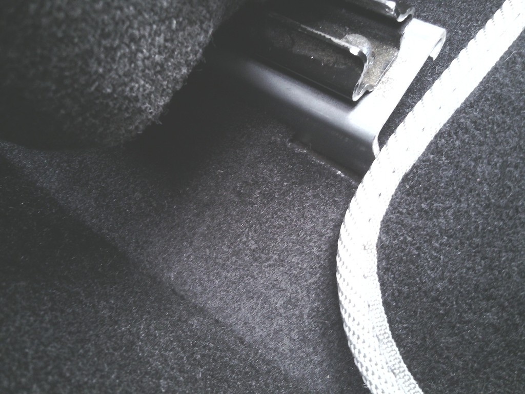 A single securing screw is used at the rear to keep the mats from moving 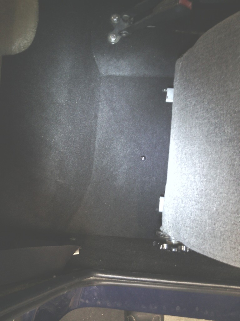 Pretty much done now so I thoought i would make a start on the rear seat, the plan is to buy new black leather / vinyl / faux leather front bucket seats but I didn’t fancy spending a fortune re-trimming the rears to match especially since the originals look like a foam seat base glued to some plywood with nothing more than a simple cover stapled over the top 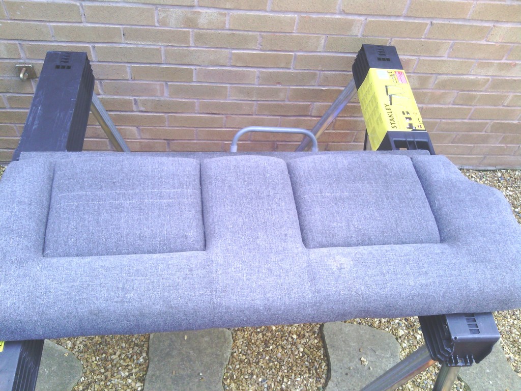 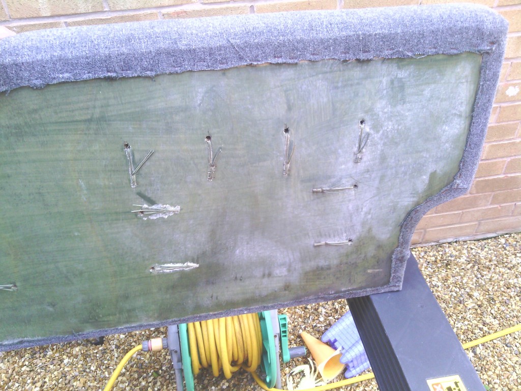 so – whats good enough for GTM back in the day for magazine features and press test drives should be ok for me to store my CDs and bags of bacon frazzles on so off I set to it, I’ve got to admit I don’t really know what I’m doing when it comes to fabrics and textiles however total incompetance has never stopped me diving in feet first before so I dug out some old but barely used seat covers we have had in the loft for the last 16 years, the last time i sat on these i was 19 and they coverd up a hideously floral migrane inducing interior in a renault Frog i once owned but sold the wife that then subsuquently exploded in head gasket faliure (Frog not the wife) and these were all that was worth salvaging.... on the upside these cost over a hundred quid from Halfords and are a very high quality in a realistic leather effect fabric that’s even foam backed so it seemed rude not to have a go at making them permanent covers by trimming them over the top and stapling them into place as per the originals – I steam cleaned the years of crud off the outer fabric and chemically cleaned it after, then plenty of staples and contact adhesive later….. 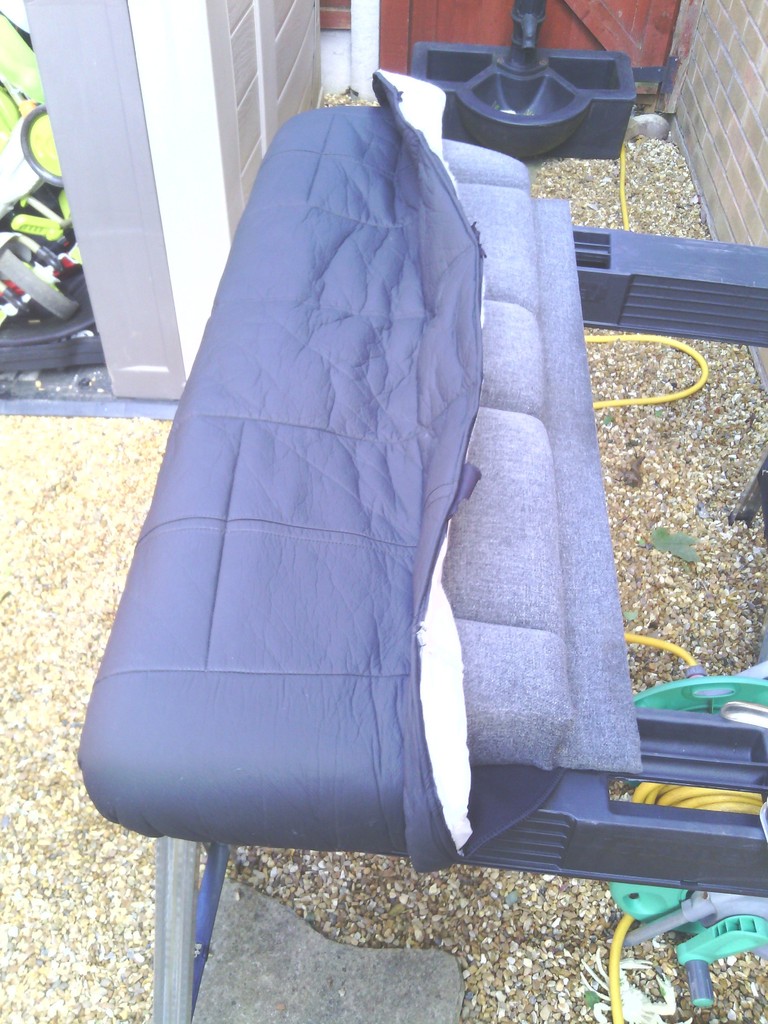 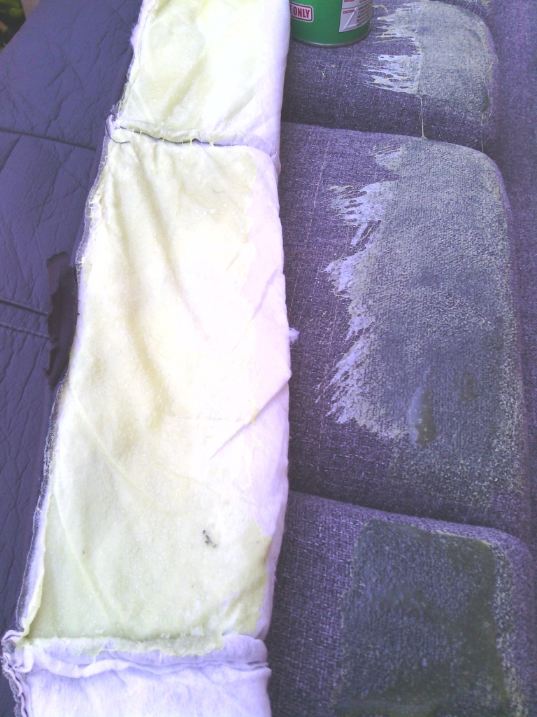 ………To a partially sighted man on a pogo stick that almost looks like a proper seat base. 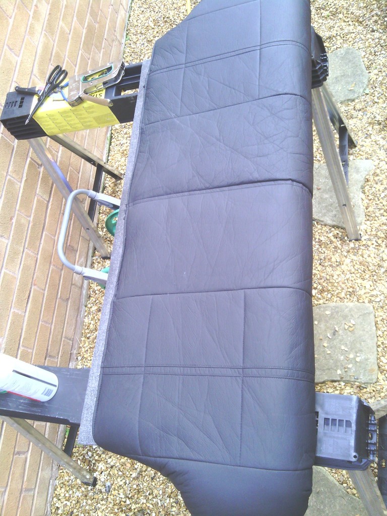 Wedged back in for now along with some generic over mats the inside is making very good progress. 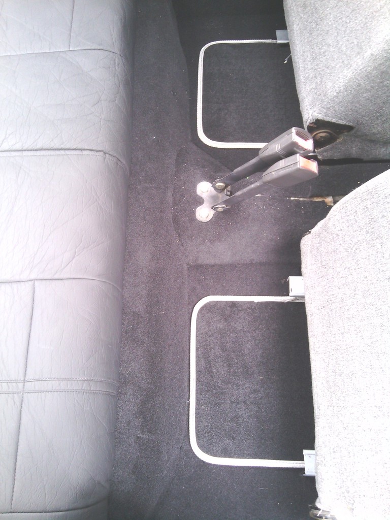 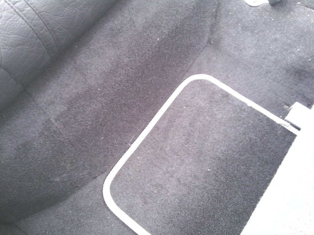 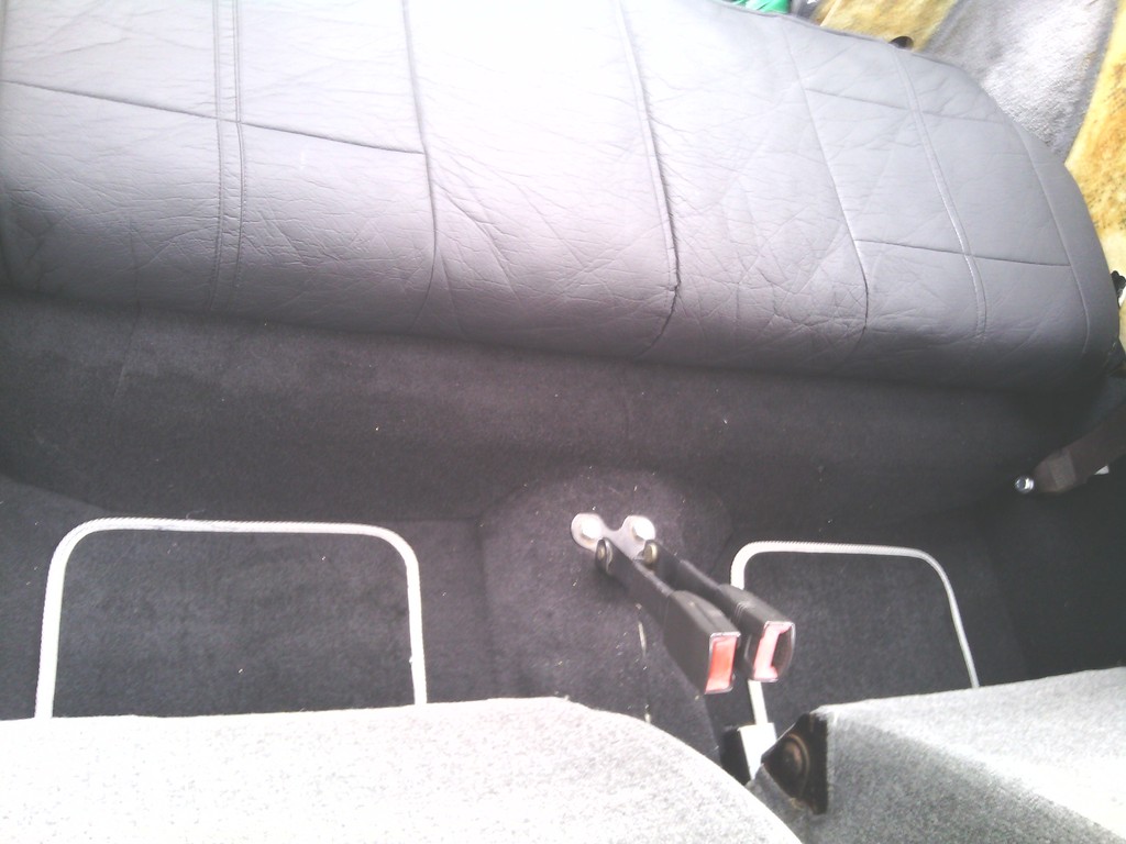 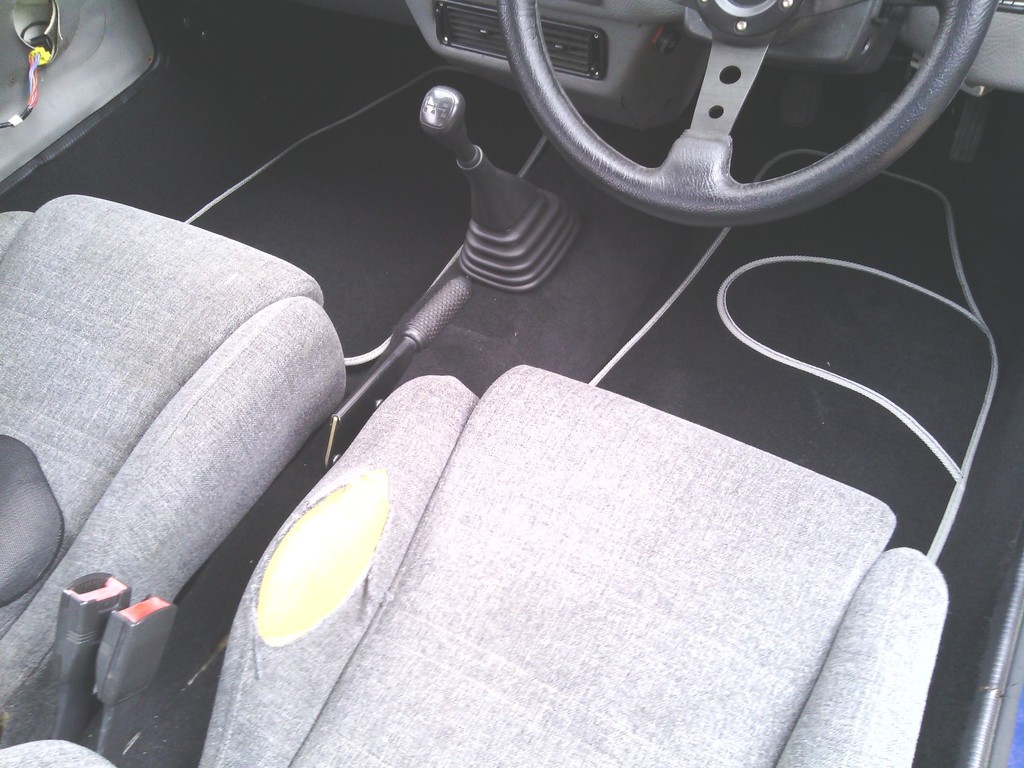 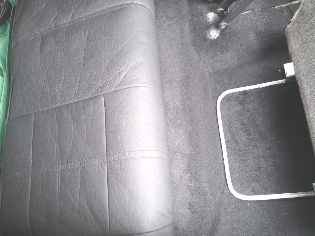 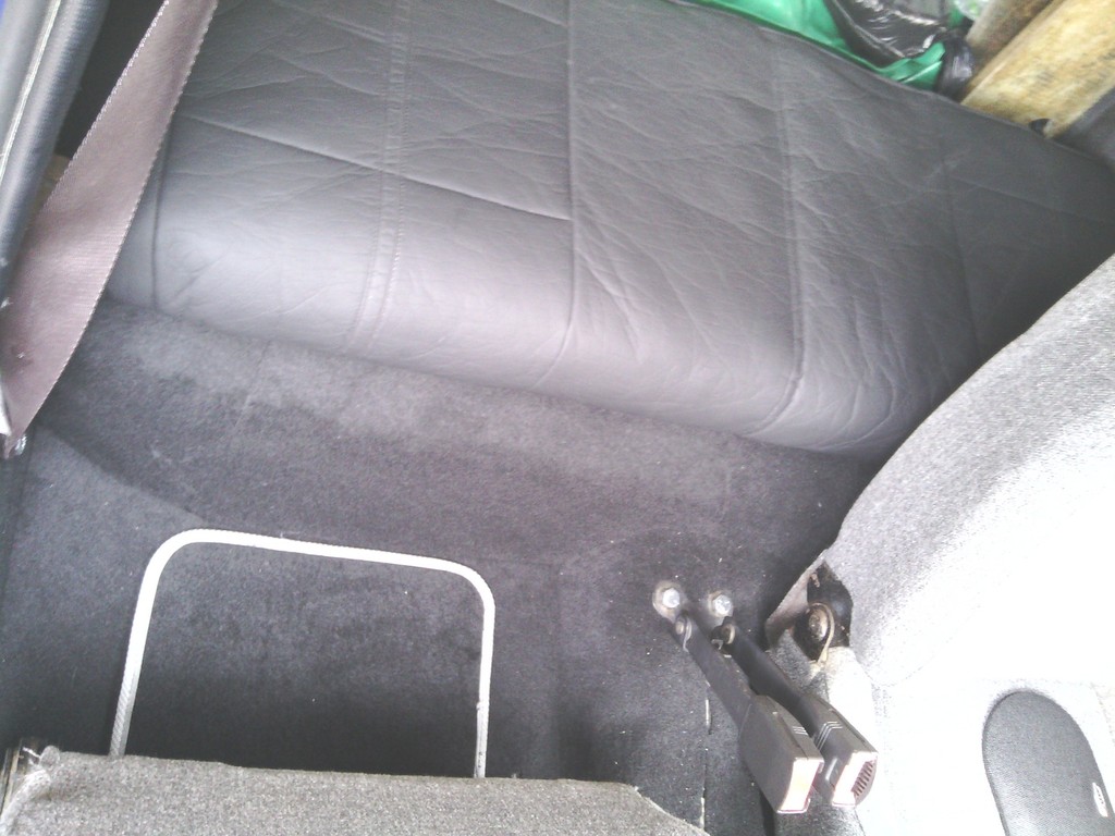 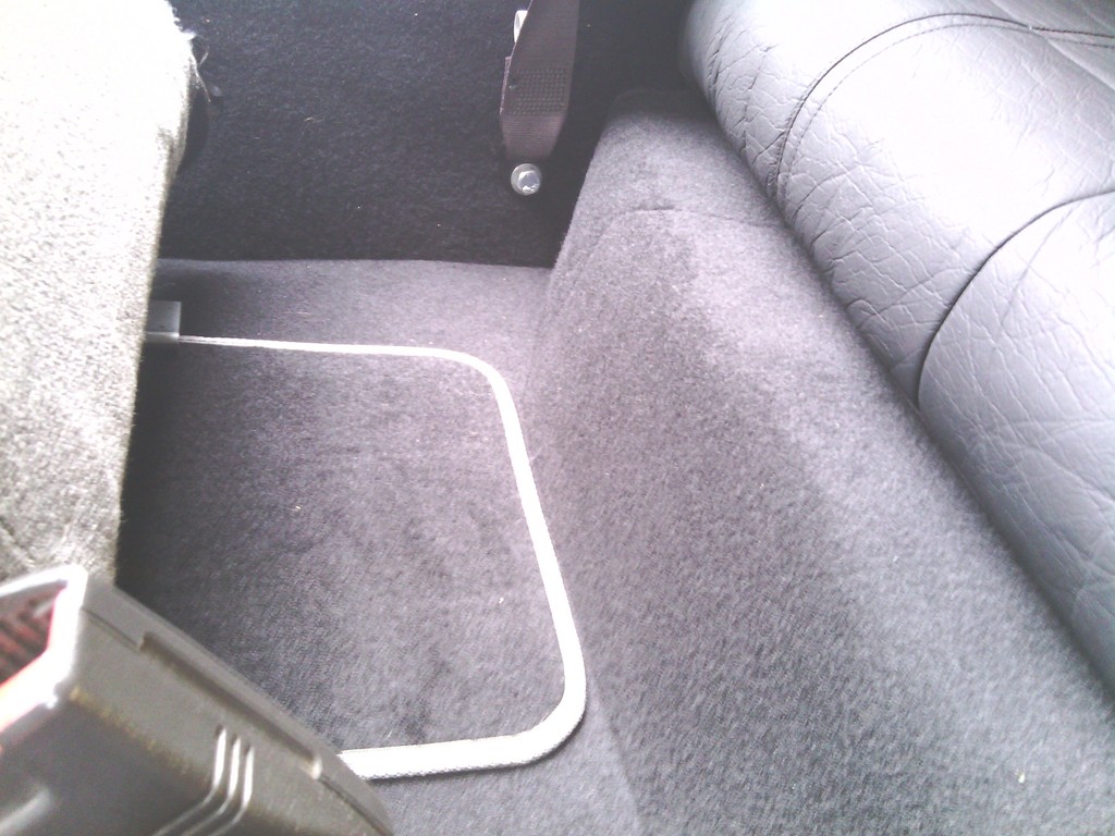 I’ve still got to finish the centre console area by making a centre console but I’ve collected most of the bits for it, the rear seat back rest will also be tackled just as soon as I’ve bought more staples and I need to cover the area where the front door hinge threads protrude into the car a bit but its all work in progress | ||
| Jin |
| ||
| Regular Posts: 159    | AUGUST 2015 More progress Left off last time with the carpet pretty much finished along with the rear seat base. In between these jobs I had been on the lookout for some new front seats, preferably vinyl / leather bucket seats. After many weeks searching I happened upon some new ones on eBay bought in error by the seller and re-listed half price, I recognised the type from when I had the Quantum and I wanted a set for that, just couldn’t justify the £350 asking price when I had a perfectly good pair already fitted – no such dilemma in the Midas, the current seats were awful to the point I considered recovering them in bin bags they were that bad, so £150 shelled out and they were on my doorstep 24 hours later 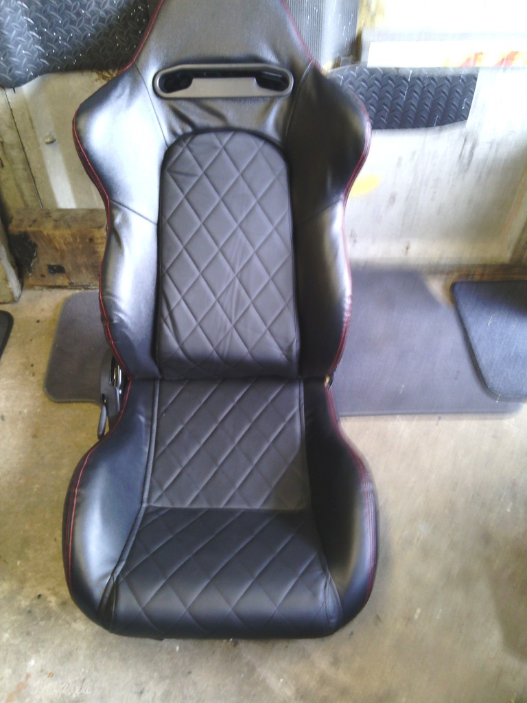 48 hours later I sold the runners from them for £45 so these have become a bit of a bargain. All excitedly I bolted one in with minor adjustments to the home made sub frame and subsequently plonked my arse on them only to find the combo of seat / me and the car didn’t work together – oh pooh 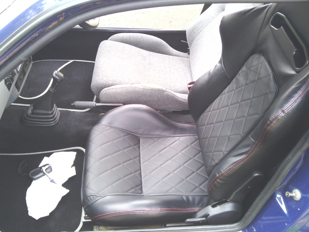 Looking at it the seat base is much thicker on the new seats so I sat around 40mm higher – may not sound like much but with only 10mm headroom to start with I need to loose 30mm off the top of my head, not only that but the rear backrest was a bit of an odd shape all padded at the lower back and the foam was made from wood (or what felt like it ) which pushed me further towards the dash further exaggerating the lack of room, the cherry on the cake was not being able to close the door due to the top section being 100mm wider for the shoulder supports and the Midas tapering in towards the top. Feeling a bit droopy I kicked the cat and sulked inside the house for a while. Once id picked my chin up off the floor I browsed the online seating retailers for an alternative and the pickings were slimmer than a racing snake especially if I wanted to recline them, so with nothing left for it I went back in the garage with the view to modify them to fit perfectly or ruin a perfectly good set of new seats. First job the height of the seat base, The standard runners were 40mm deep which I copied in better steel when the originals fell apart upon buying the car, not only that but they weren’t positioned in the car well enough considering I had the seat pushed further back due to being 6’ 2”, the white marker on the sill shows the centre of the seat base position in the position I require for driving in relation to the runner supports. 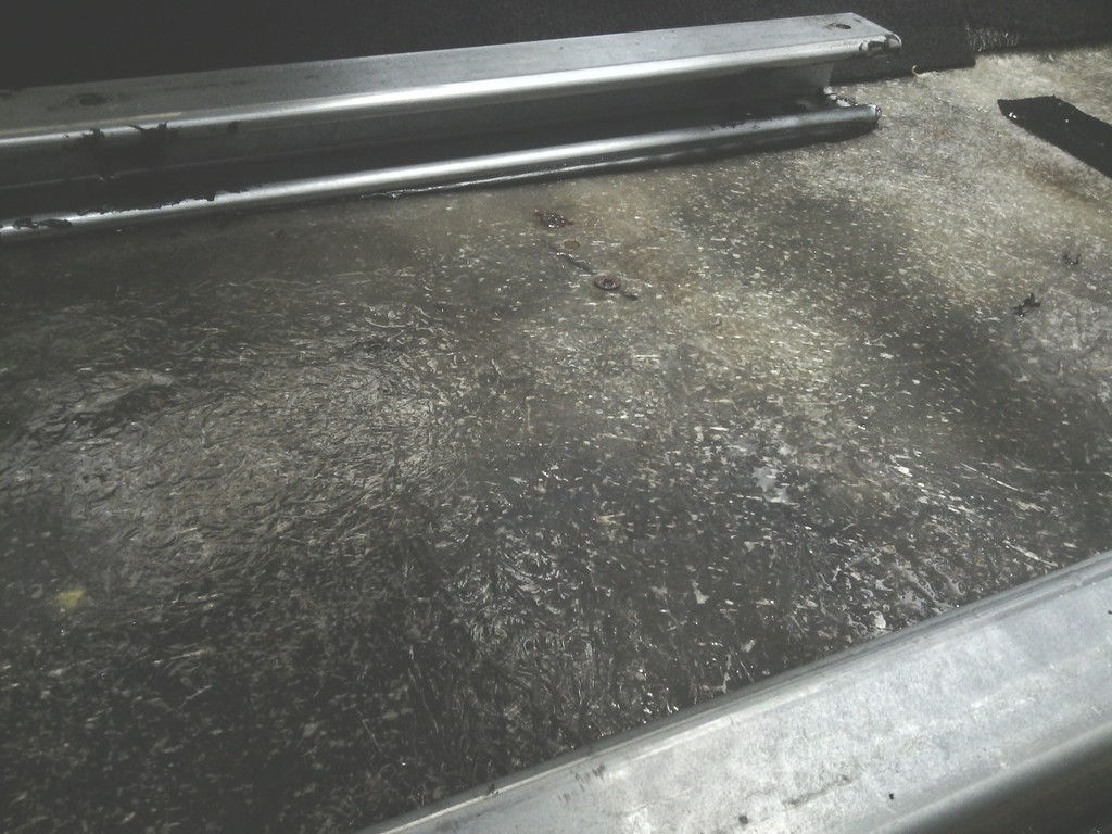 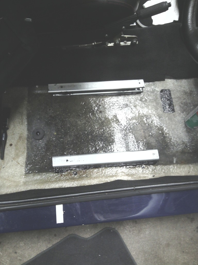 Not ideal, there was some floor flex, So 2 new runner supports were made from 50mm wide aluminium plate which is better than the standard 40mm wide ones and they were extended 50mm further back down the car to spread the load 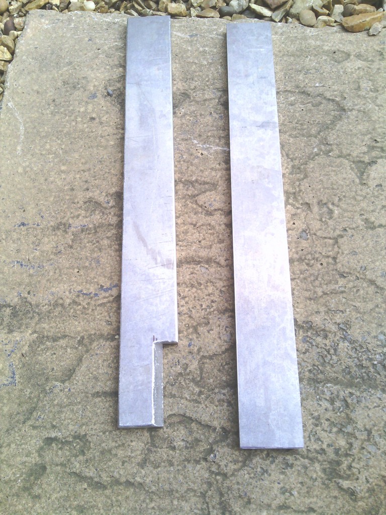 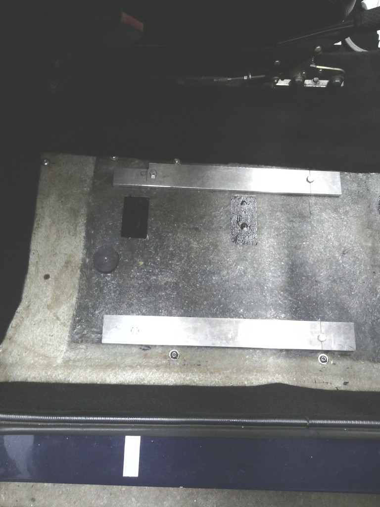 That’s better, the new supports are 10mm thick giving 30mm extra head room, 10mm is the limit as this is the thickness of the sound deadening of the carpet anyway. Second job, the backrest. I unpicked the cover and extracted the foam from within 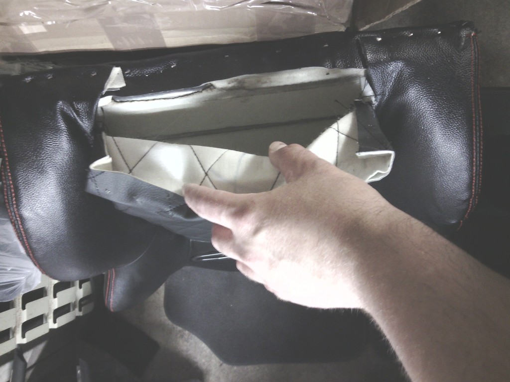 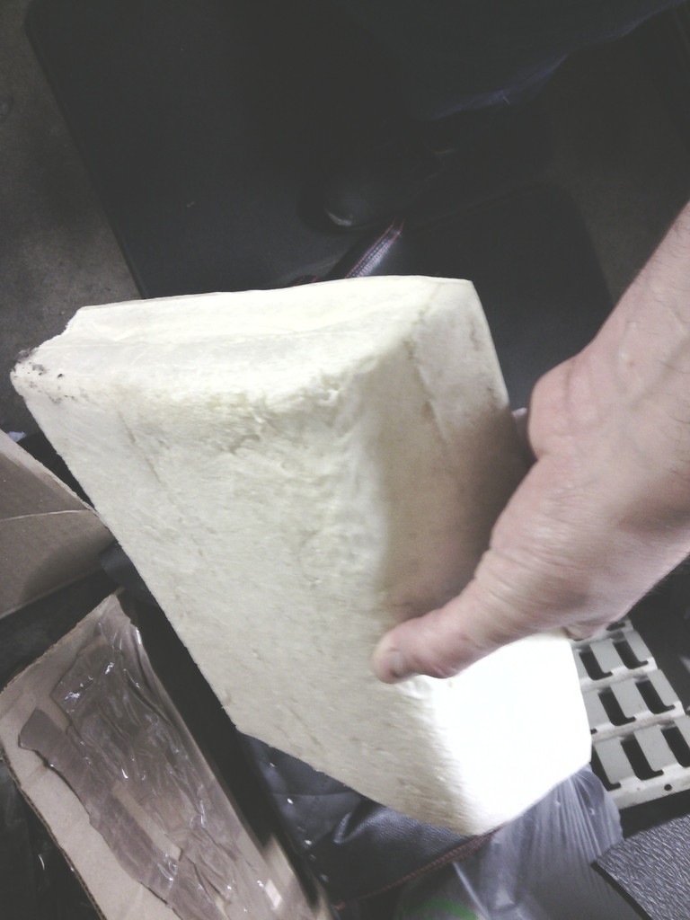 I’ve sat on comfier brick walls and its far too thick at 2” , so now to find some soft foam to re-do it. But not as easy as you would think, trying to describe squishiness over the phone aint easy. until a chance trip out for baby supplies one day threw up this 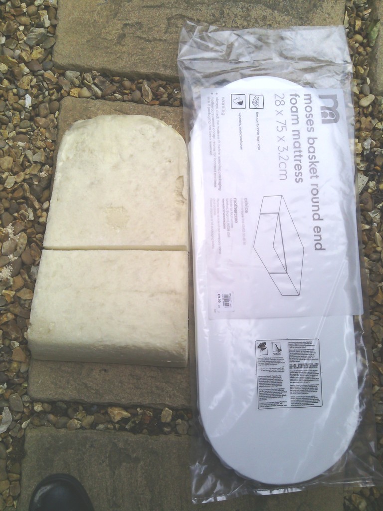 Don’t worry; im not all selfish I’ve given the little un some old car mats to sleep on instead. Soft enough for a baby to kip on so perfect for me, chopped to shape and glued in and the transformation is complete, the shape is re retained but the size deforms back to lose the 2” in use rectifying that problem – comfy too. 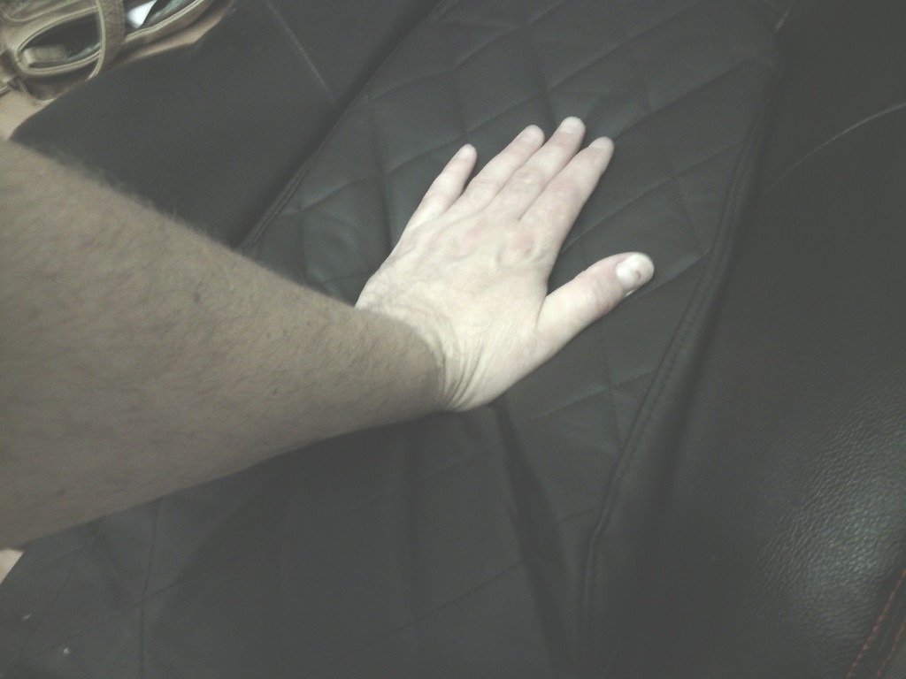 Lastly the width, I’ve considered a few options but for now I’ve chocked up the outer 2 bolts with 5mm spacers, not too much to effect driver position but enough to cant the top edge in to within the door line of the car, as soon as I get chance in the next fortnight ill remove the top cover and tweak the shoulder supports in by 50mm each side to be the same width as the old seats. Regarding the fitting, a tip I wish I carried out on the Quantum was to replace the seat sub frame bolts with studs, makes locating and removal so much easier. 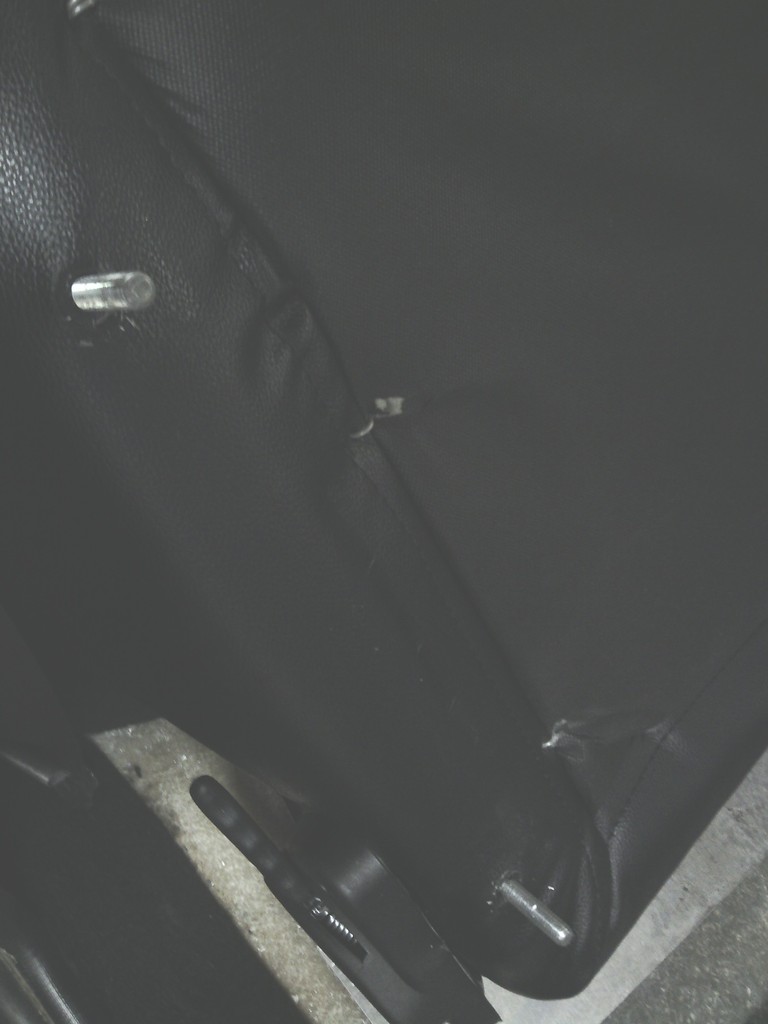 I was glad to get these out the car – dread to think what some of those stains are 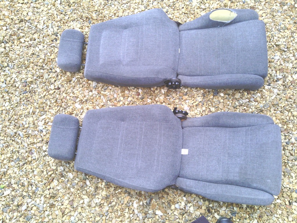 Rear seat back re-trimmed as per the base and that little lot is not looking too bad now, the old back ret looked like it was host to a wrestling match between a rabid badger and a psychotic bear 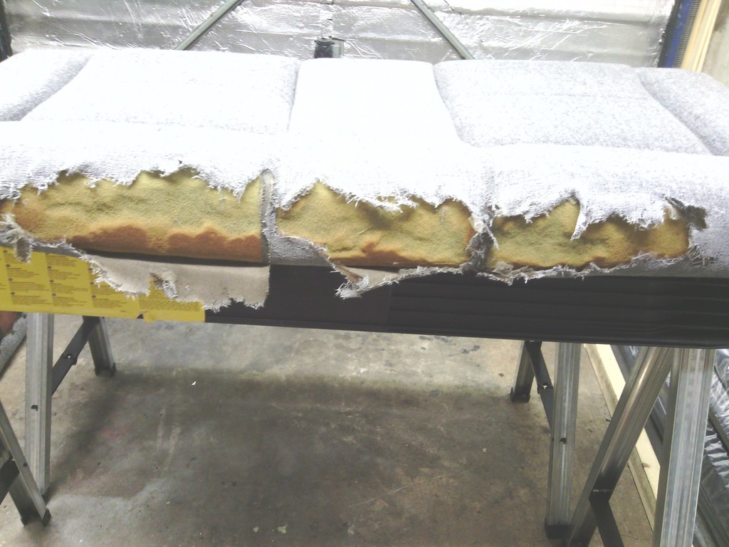 Old rotten fabric trimmed off 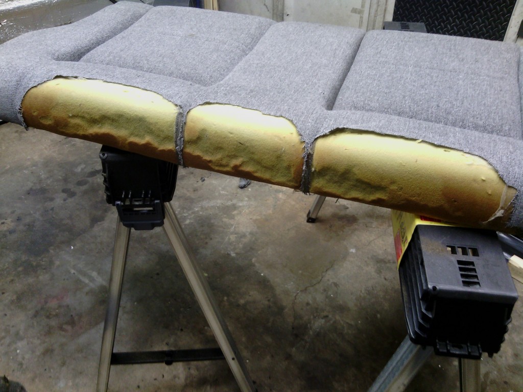 Trimmed up 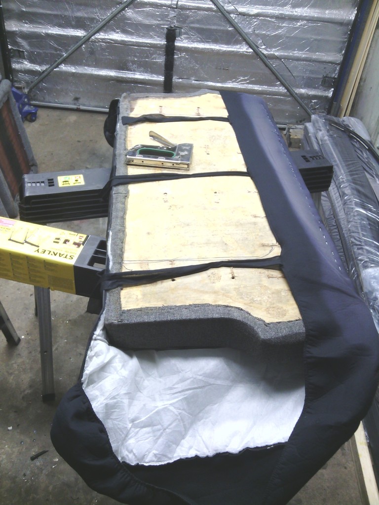 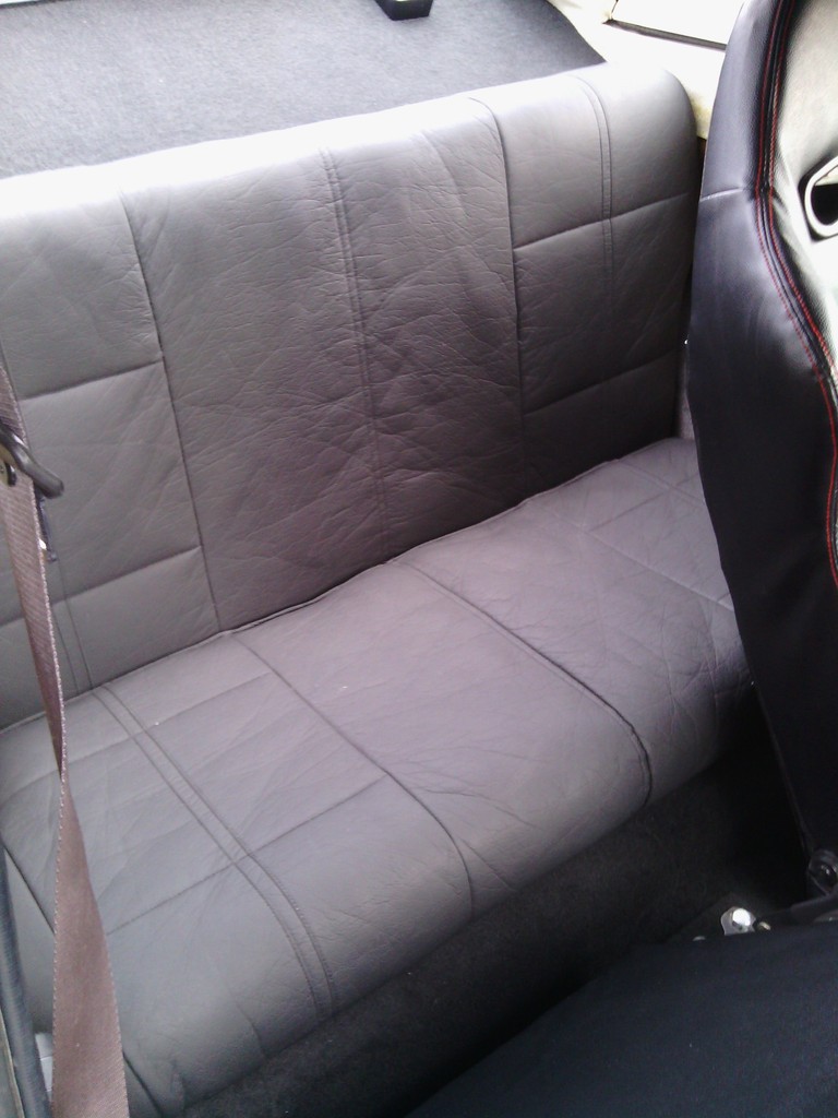 At Stoneleigh I found a nifty roll top storage box on the CBS stand 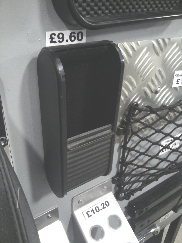 Great idea especially since storage space is at a premium limited to a downward sloping ill-fitting glove box that spits its contents out on the passenger floor when you hit a speed bump so this will come in handy 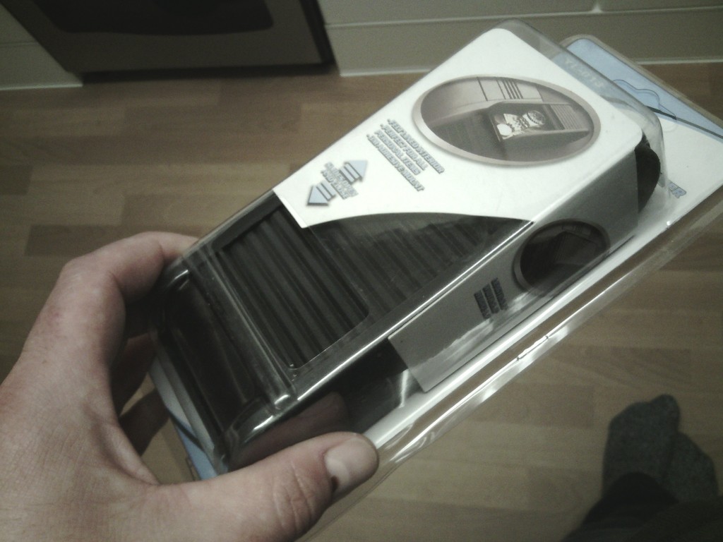 £2.50 delivered from eBay HK Fitted on its own custom mount 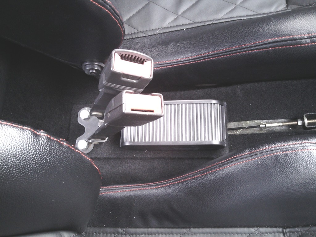 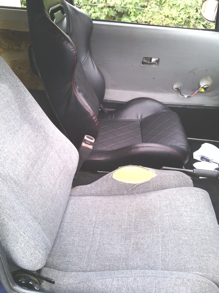 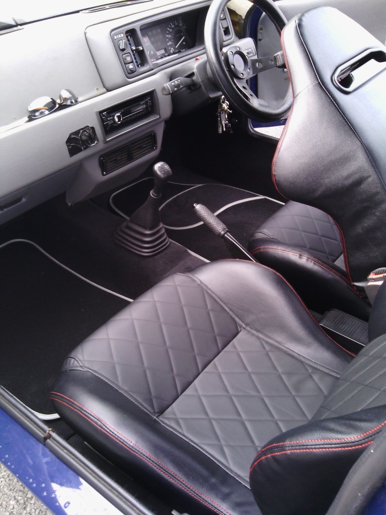 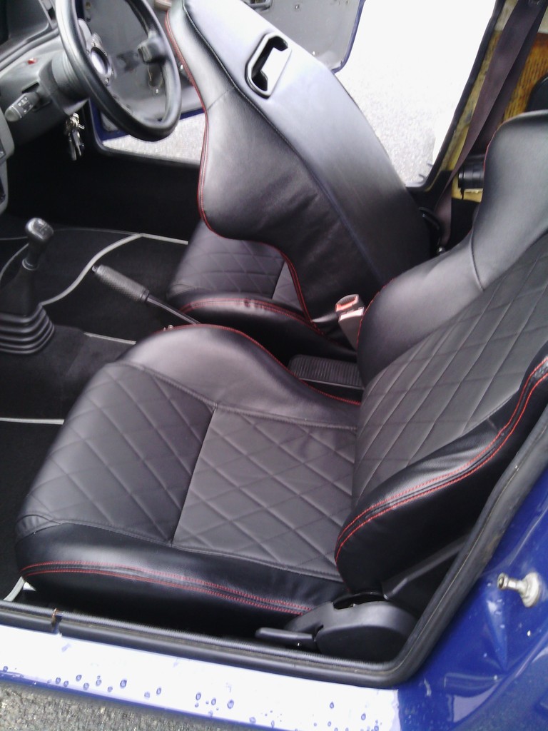 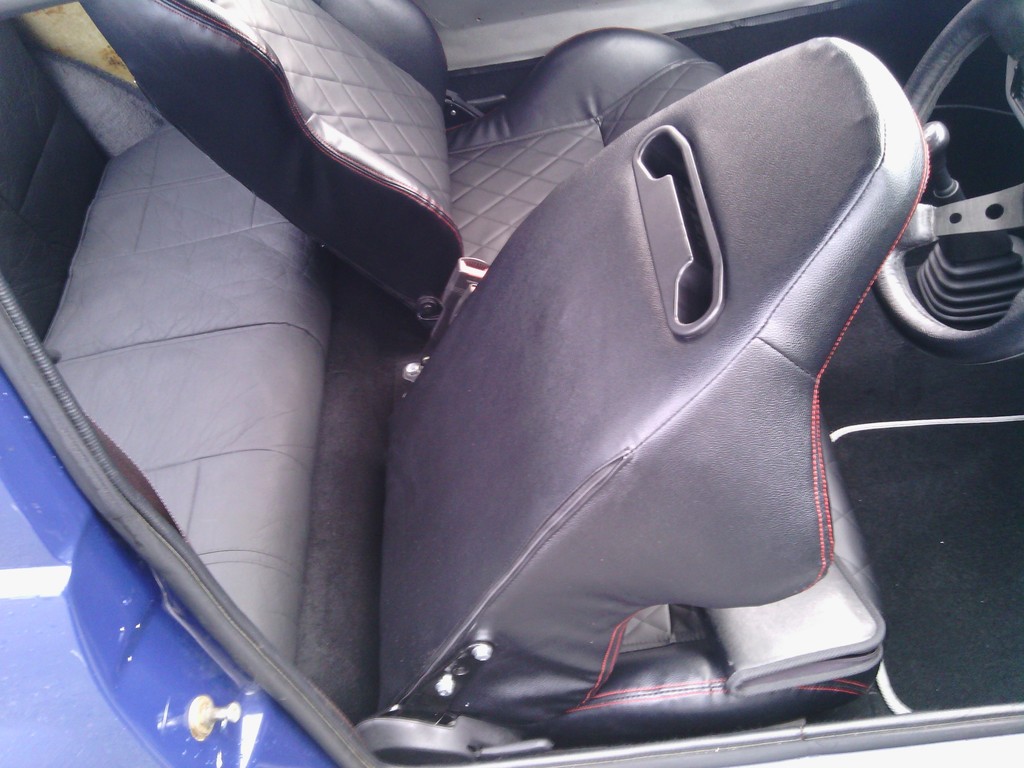 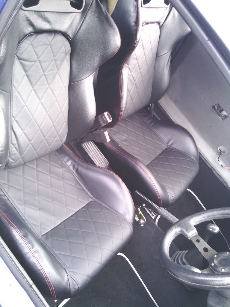 So that’s the seats and carpet almost done – onto the door cards These have given me a headache since I pretty much bought the car, not only were they too deep and got trapped in the door shut but the fit was terrible, 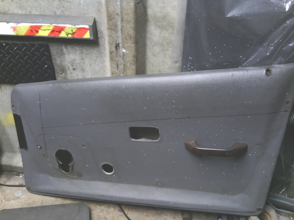 After trimming off the excess marked at the base I set about making some adjustments, first to go was the door pockets, they didn’t fit anyway due to the contoured nature of the Midas door cards leaving gaps all round and the old ones were in such a state id need to replace them anyway, so they got binned, so did the old land rover door pull handle that you had to be a contortionist to use to close the door anyway so this was no hardship, I marked out where the steel frame sat behind the door card with the idea being to secure the door card on using concealed fasteners to do away with the series of self-tappers currently holding on (and not in some places) the periphery of the door card, 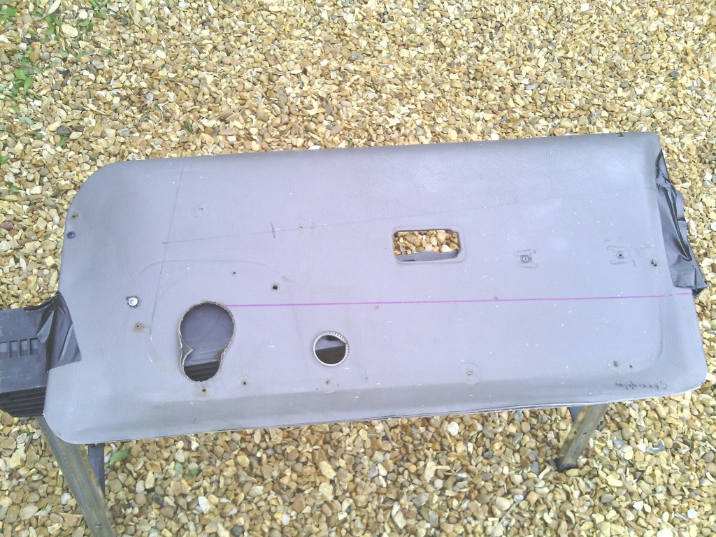 A couple more adjustments made to clear the door glass 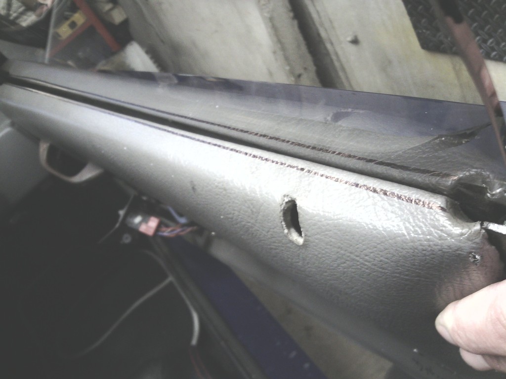 And some tweaking of the card itself, there was a 20mm gap at the widest point in the middle where the card didn’t sit flush to the door  Must be an age thing, so I corrected it by clamping it with wood at the base and weighting the card to pull the bottom lip in tight to the door, a fan heater was left on all night to soften the fiberglass to allow bending, Don’t worry, full safety precautions were taken regarding the heater –I made sure the wife was out for the weekend first…. That sorted I had to find new inner handles, I wanted something more modern looking so opted for some MX5 units, 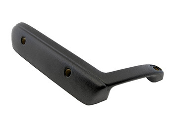 3 fixing bolts are used on these so I marked out and drilled into the steel frame inside the door through the door card then tapped the hole M6 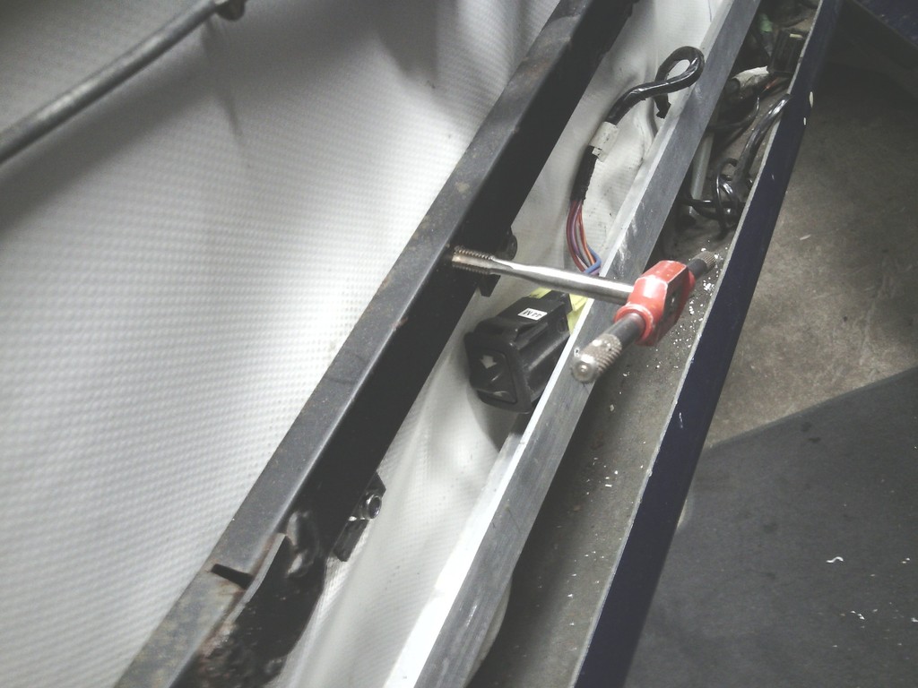 Fitted studs to them to reduce strain on the fixing and locate the door card easier, the upper handle bolt needed a small bracket making to tie in to the inner door frame 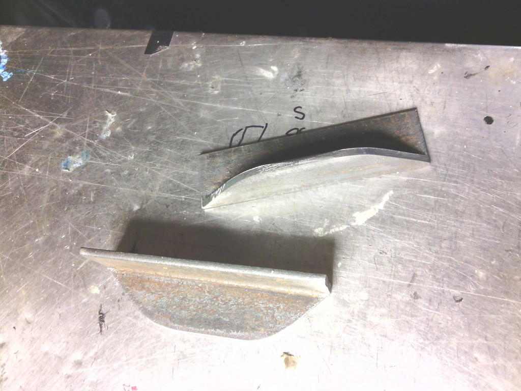 All 3 fixings in place 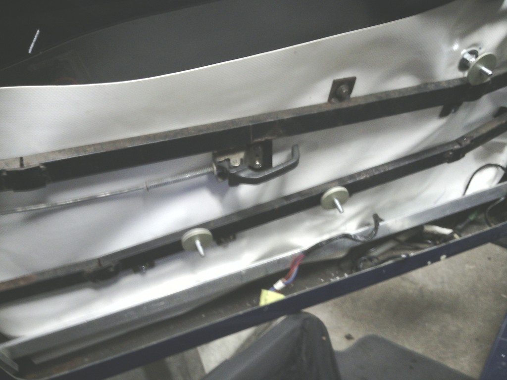 This set up looked better and offered an arm rest, something I was lacking, but left no space for a door pocket, not much of a hardship because with the new seats I’m lucky to close the door anyway but the old pockets also housed the speakers and electric window switches, The speakers won’t be too much of a problem, I’ve ordered some 5.25” units that match my rears with their own grills so all good there, the plan is to use one of the speaker grill screws to secure the lower front corner of the door card to the alloy frame I made some time ago to secure the door card Again a subtle fixing, but the electric window switches needed some thinking. Then I noticed the MX5 handles were hollow so a plan was hatched to mount the switches within The old ones were too tall to fit in the small space inside 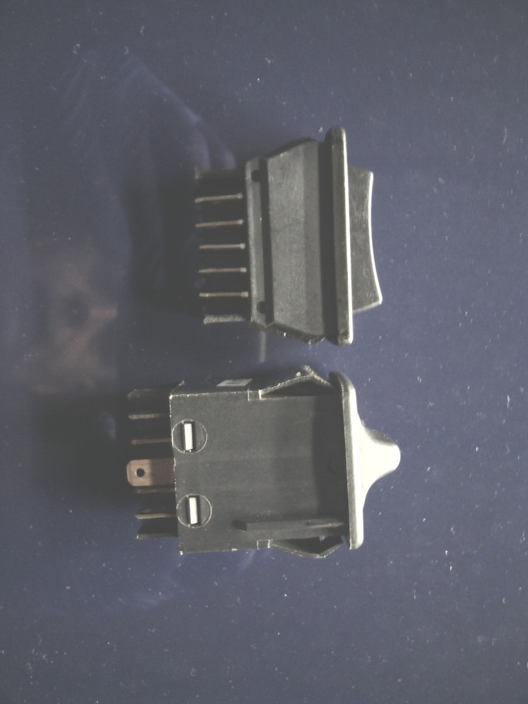 I bought some replacements with the intention to rewire them into the car but much to my amazement with a small modification to the new switch the rover plug fits straight on – so totally reversible if needed The handle was hollowed out with Stanley knives and nerves of steel; I almost lost 11 fingers – 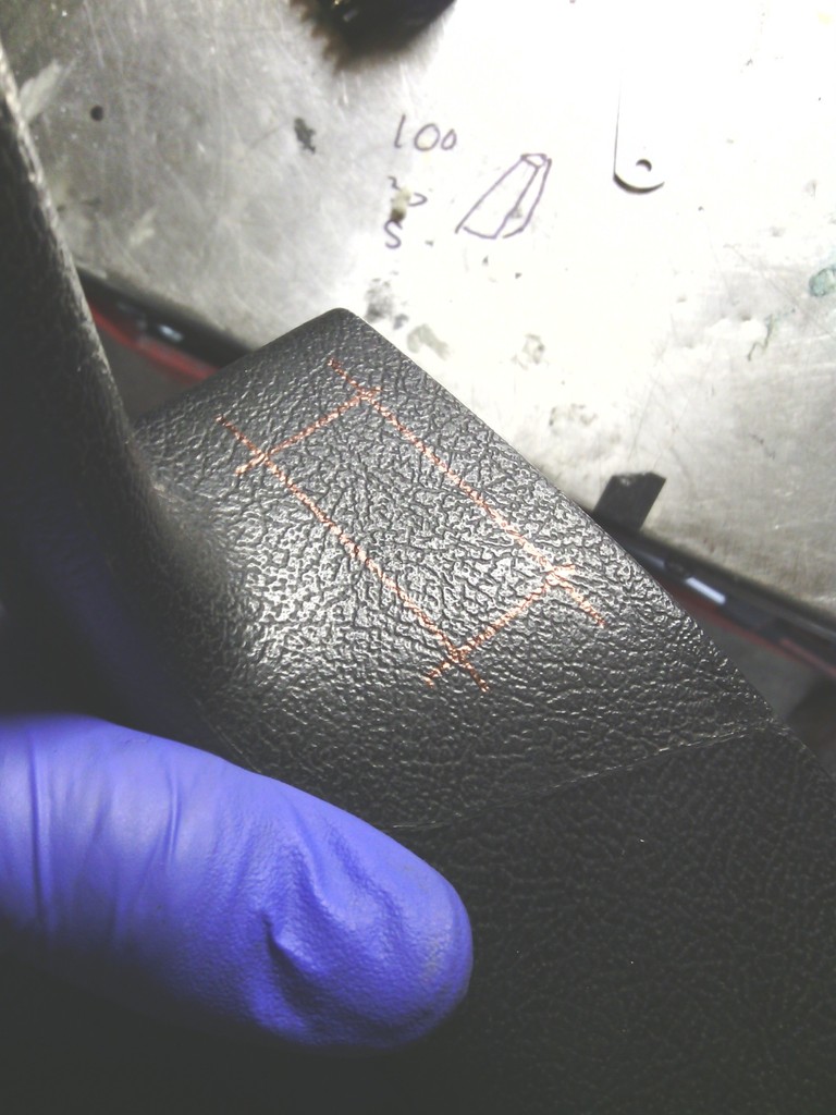 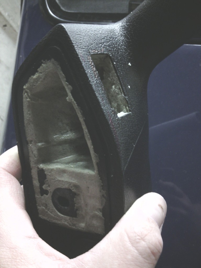 Plugged in and all fitted on the whole assembly is much neater. 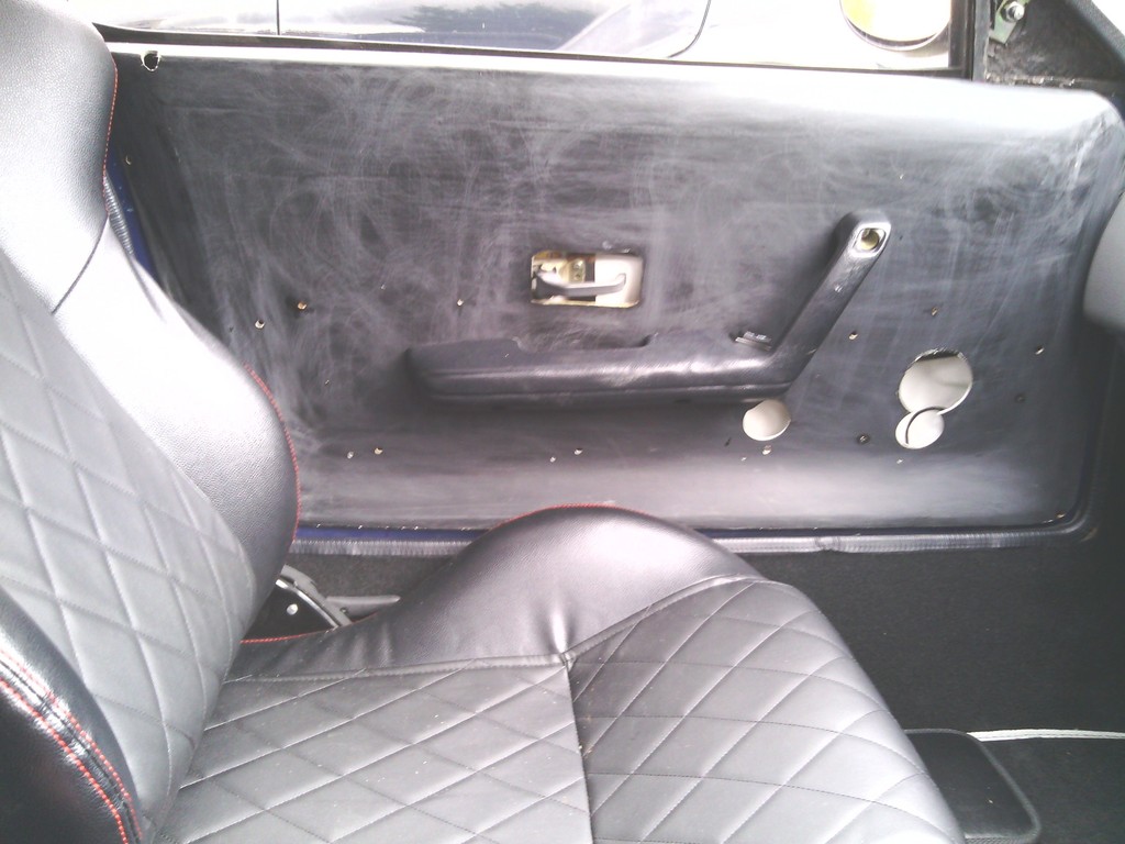 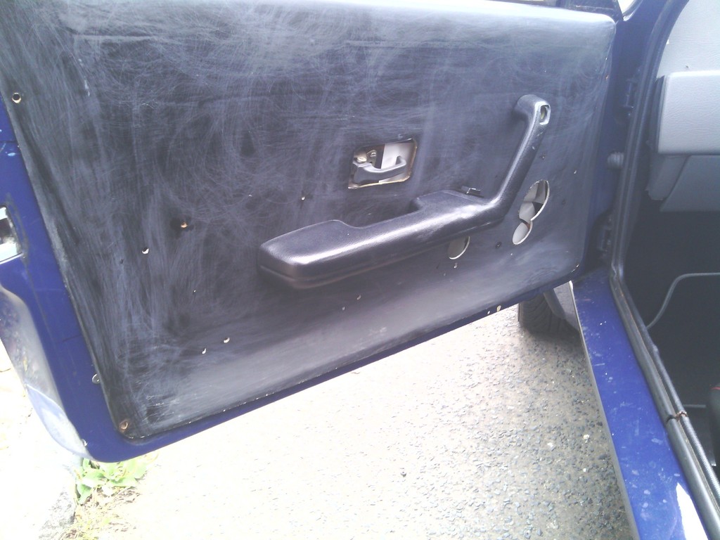 It would have been nice to keep the double switch on the drivers side but there was not enough room in the MX5 handle to do so, anyway since I can reach the passenger side door without fully extending my arm I don’t think its too much of an issue. I’ve ordered a small LED courtesy light to fit to the rear of each door to offer more lighting but more importantly to secure the rear lower corner of the door card to the door but to be honest such is the amount of work carried out to make them fit better they fit perfect with just the handle screws, any more is just a bonus. Next to do – re-cover the cards and fit speakers and rear inner side panels – retrim the dash…. | ||
| Jin |
| ||
| Regular Posts: 159    | SEPTEMBER 2015 I left off last time having almost finished the fitting and trimming of the door cards which I’m happy to report now fit perfectly, while on to the fitting, I did mention the intention to utilise the lower speaker bolt to secure the door card to the alloy frame I made inside the door, the 3 remaining speaker bolt holes had tapped M5 threaded plates bonded on 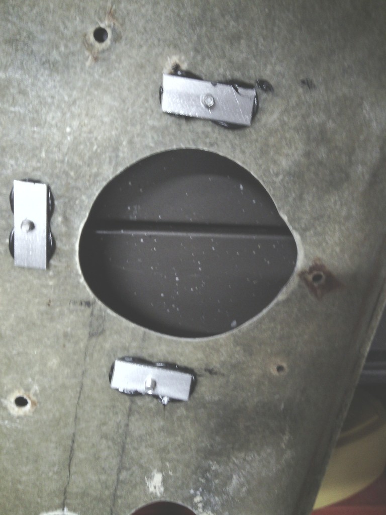 And the lower one fitted up and worked a treat 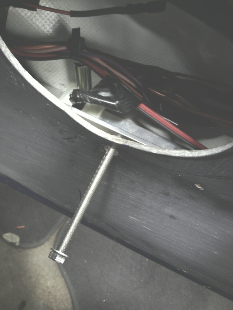 I also mentioned the LED interior lights that would also act as a securing point for the lower middle section of the door card; these were wired in with some nifty JST connectors 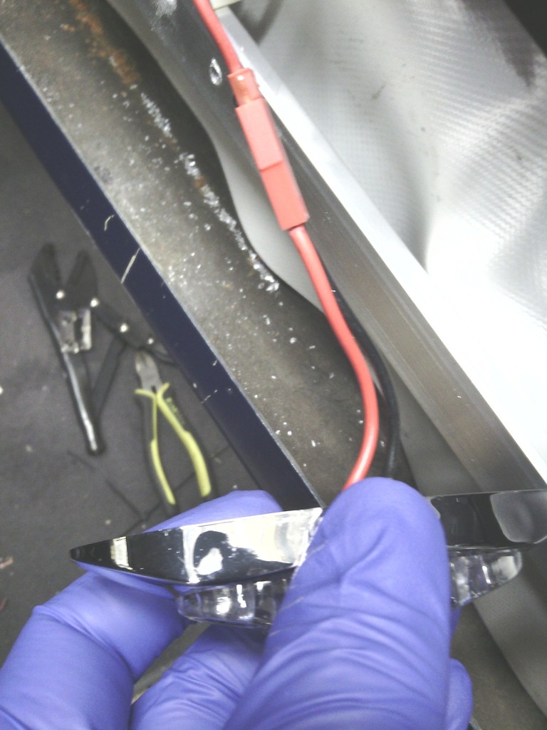 The 2 mounting holes for these also fit into the inner alloy frame I made inside the door These 2 improvements now mean the door card sits nice and tight to the door and there are no visible fixings holding the door cards on at all. With all the fitting done it was time for trimming, I pondered this for ages, strong contenders were white, cream , tan and even light blue, I certainly didn’t want dull grey or black, but in the end I kept coming back to red in my head, helped in part by the red stitching on the seats too, I got loads of samples to look through. 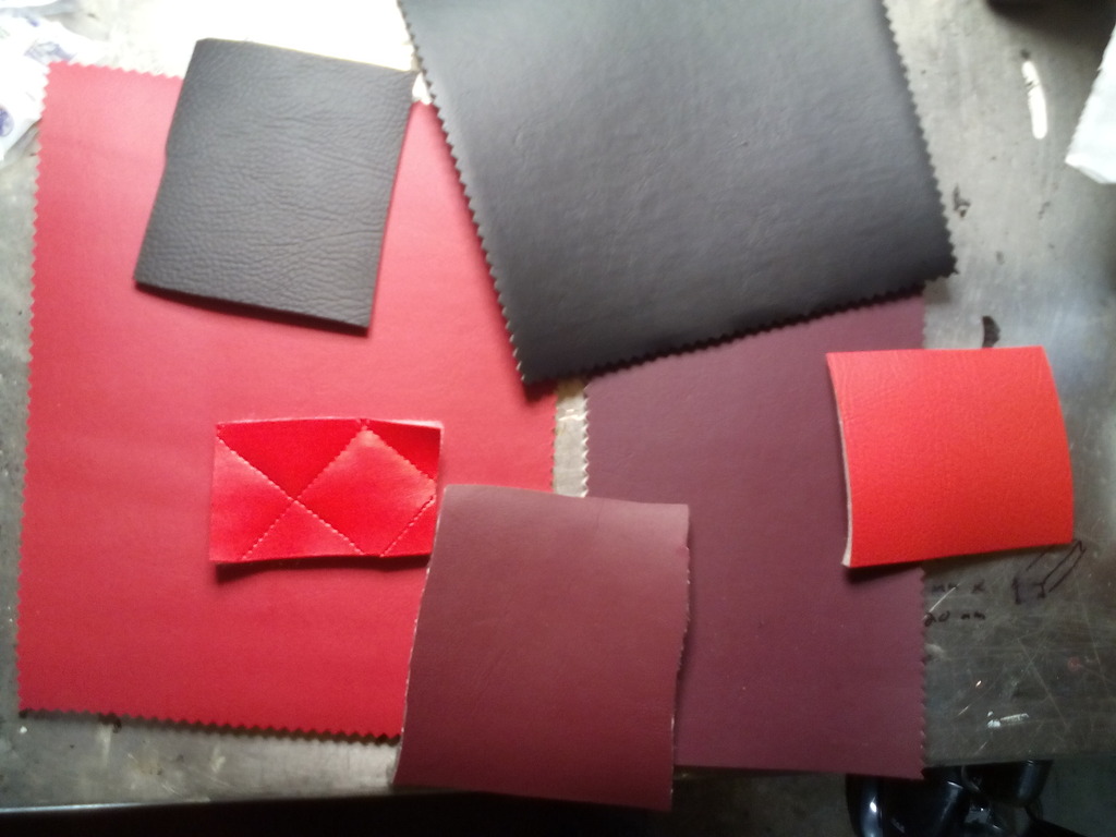 And I’m glad I did because the quality varied widely, I had decided from the outset I wanted foam backed vinyl because it would hide imperfections and help fill in the gaps around the fittings, one of my gripes with the original door cards was the wonky nature around the edges and gaps around the handles, the padding will also add to the quality feel. I couldn’t find a red I liked easily, some were too dark with an antique look to them, some were salmon pink in some lights, and it was risky that plain red by itself may seem a bit much, but working with the diamond stitching on the seats I thought I’d follow that through to the door cards also, so a few meters of diamond stitched vinyl on a 3mm backing was ordered 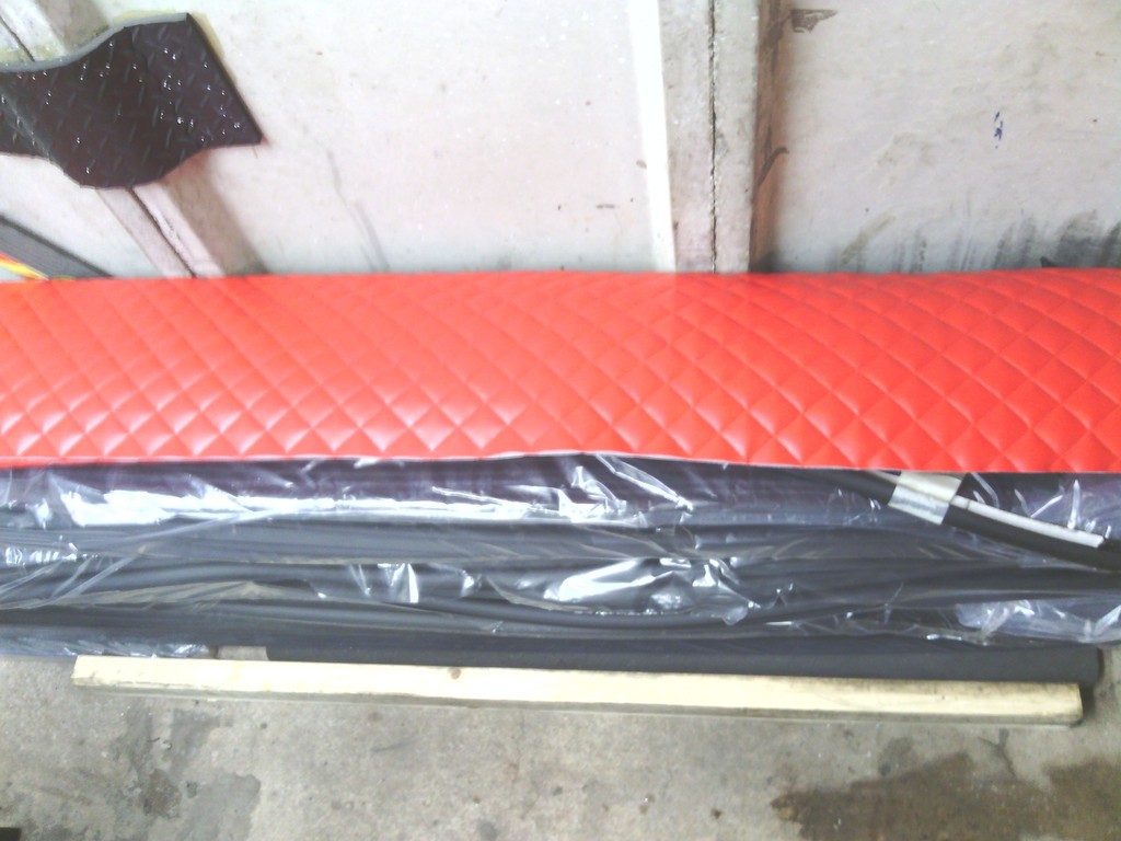 And I set to work 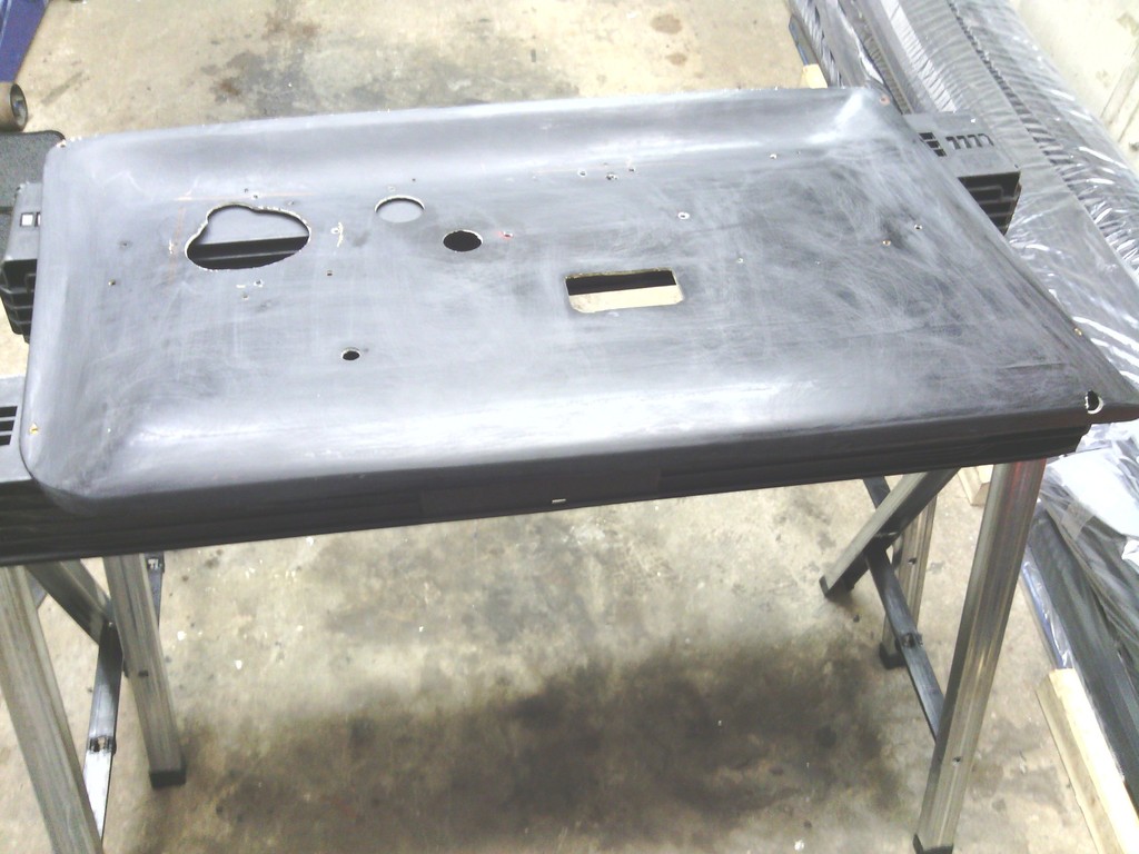 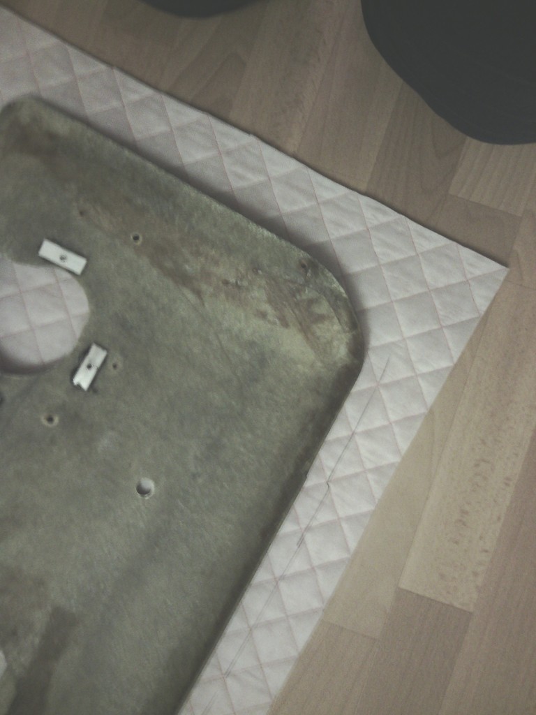 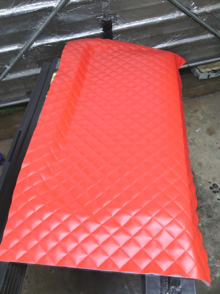 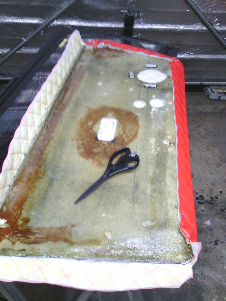 Bonding this stuff is a bit of a pain since it’s not foam backing that’s bonded on it’s a stitched on wadding which delaminates itself as you glue it, I got through a fair bit of evostik in the process but the result was worth the effort 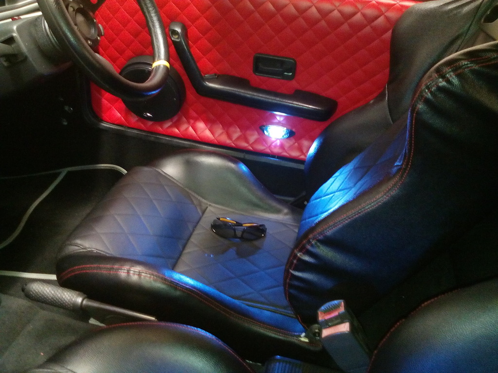 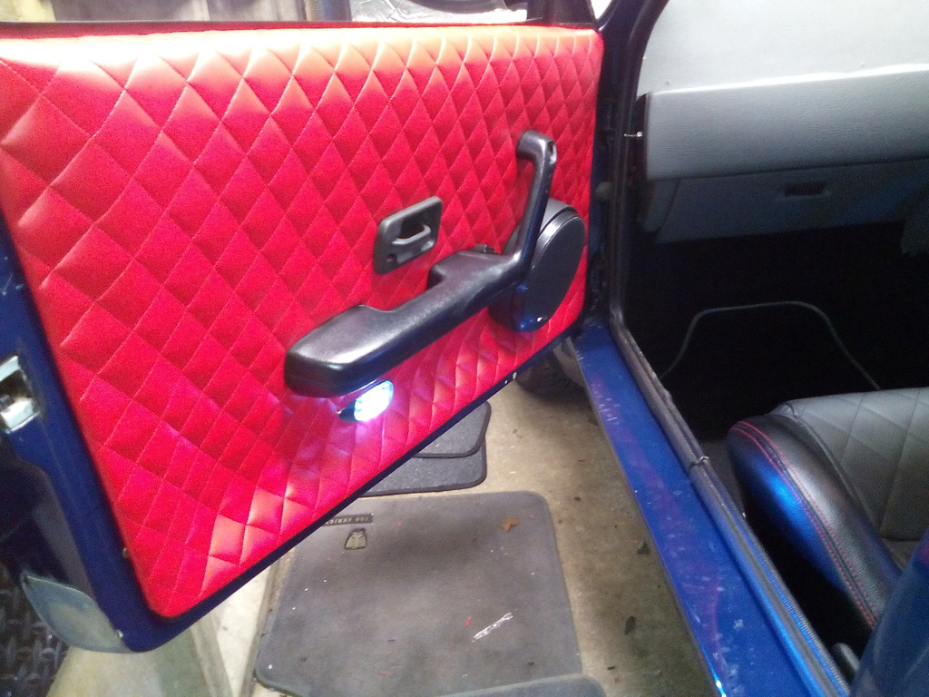 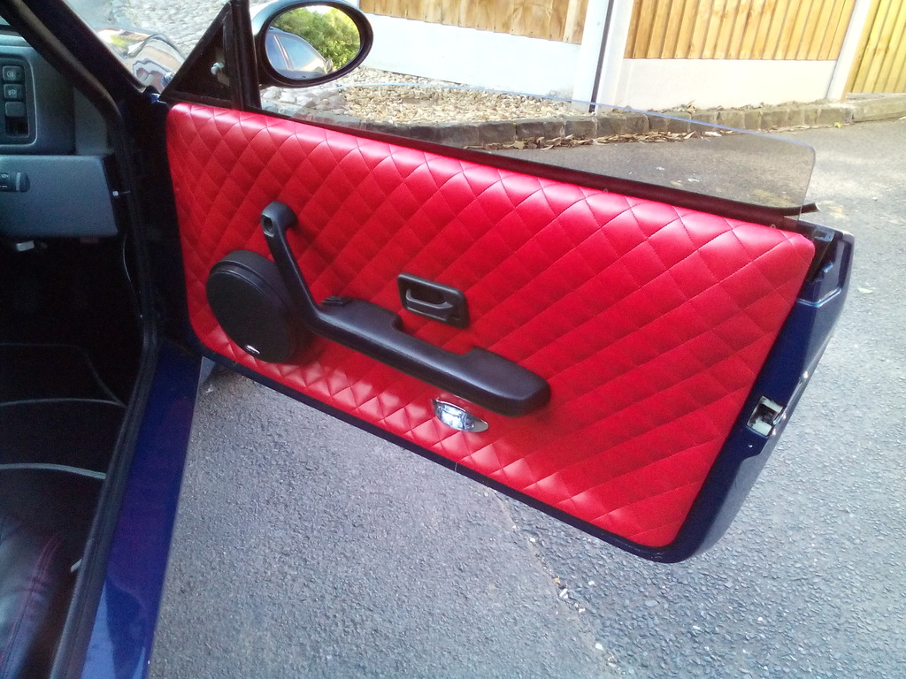 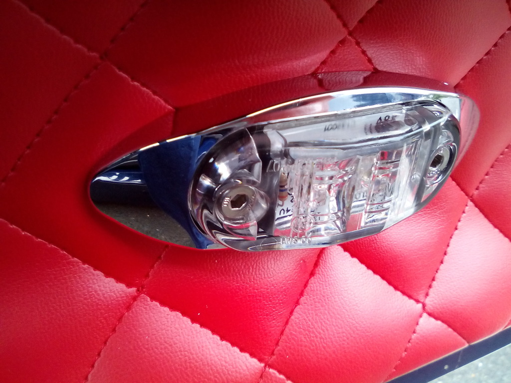 The speakers didn’t fit flush to the door card due to the steel frame inside so I bought some mdf 30mm spacers and covered them in nice stretchy vinyl 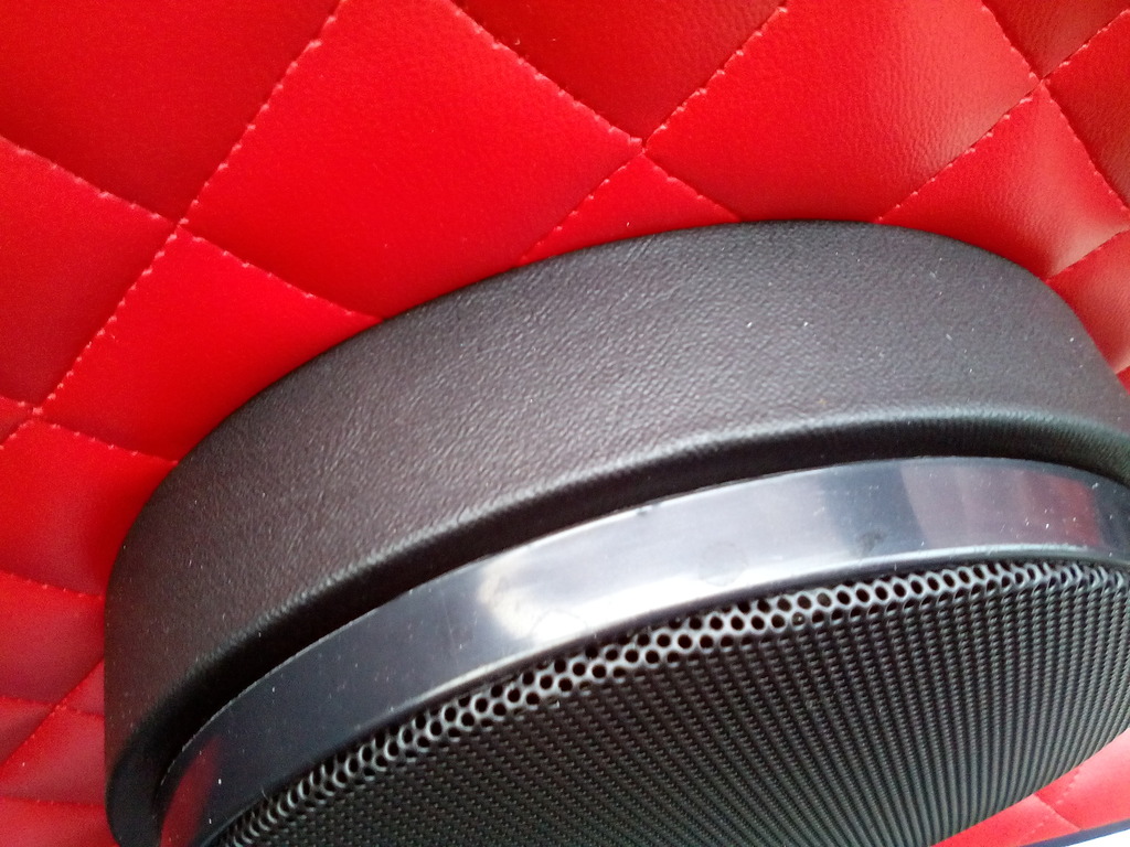 The result is better than I imagined, the illumination from the led lights is amazing too, with those and the mirror lights the car is very well lit up now – a far cry from no illumination at all when I bought it, finding a good location for the door switches was a bit of a headache, I didn’t want to drill the A pillar to allow another route for leaks, drilling the doors would be equally tricky an maybe not successful due to the profiled shape of the A pillar the switch would have to bear against as its stepped and could cause the switch prong to snap, in the end I went against convention and added them inside the door line on the ends of the dashboard sides, these have the added bonus of holding the end caps on as opposed to them being glued on as before – handy since I’ll be removing these soon to trim the dash, you can’t see them with the doors closed either – job done. 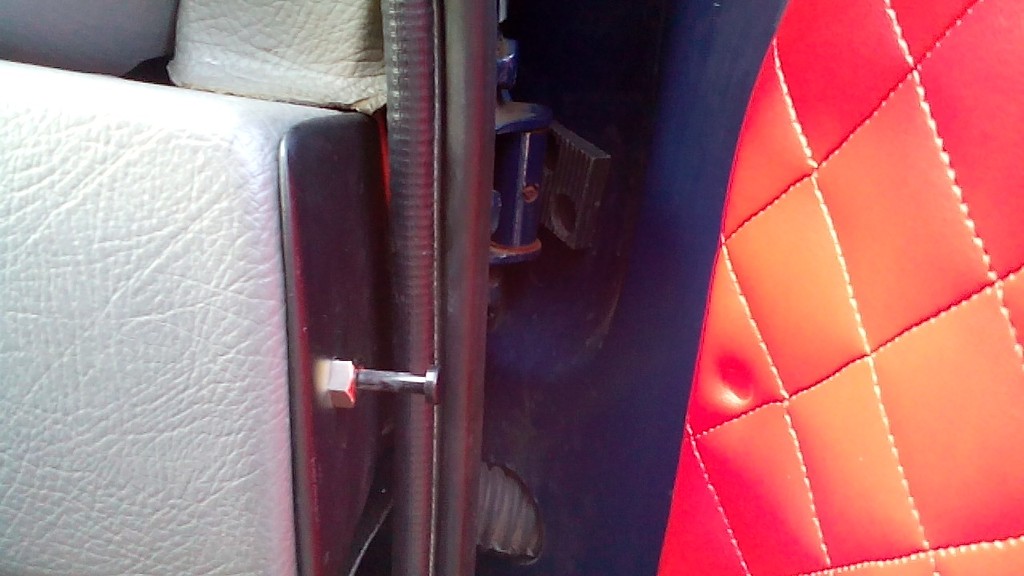 I’ve even made the rear panels, the originals were just carpeted and glued on, I didn’t want to do this as its seems a bit of a short cut, so with all the rear stripped-down I made the first template 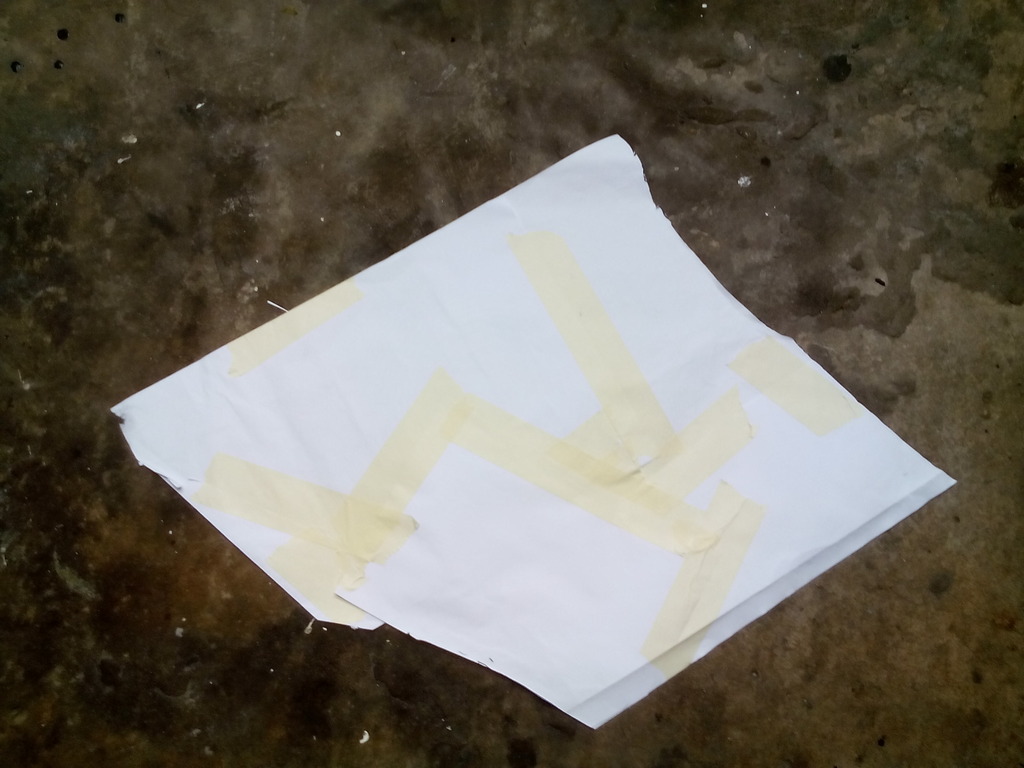 And the first panel 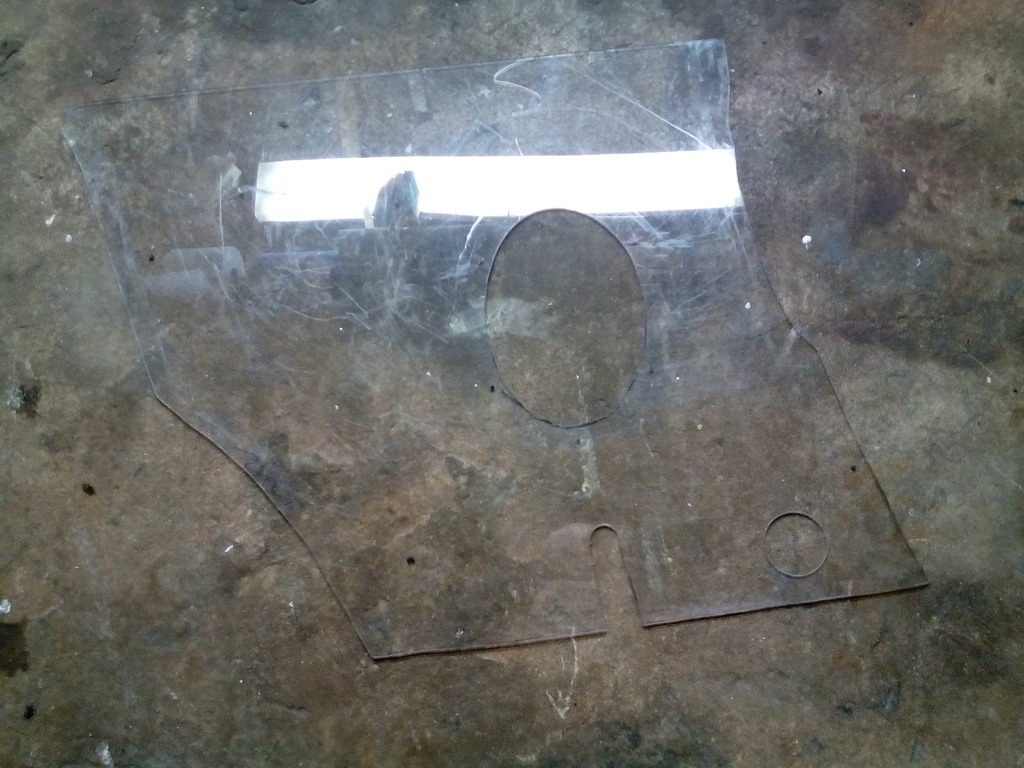 , I chose the thinnest sheet I could get while still retaining strength, this was due to the small nature of the car anyway and every mm would count. I chose clear polycarbonate because is strong, wont rot or wear but the big bonus with it being clear is it makes marking out the fixings behind such as the speaker holes (which incidentally will be used to fix the panel to the car) and seatbelt mounts a doddle, Both are made now and ready for covering, Both rear panels made and covered, which was no easy task since to minimise thickness I had to trim back the padding on the return edge all round 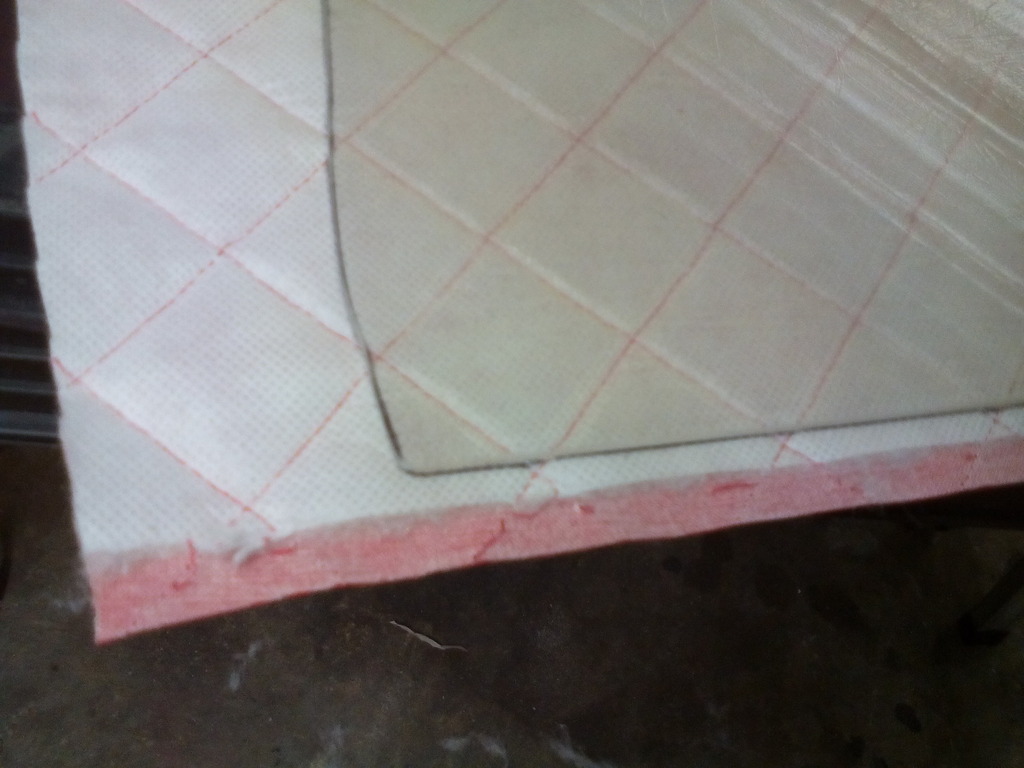 Then each run of stitching had to be sealed with a dab of superglue to stop it fraying - took forever 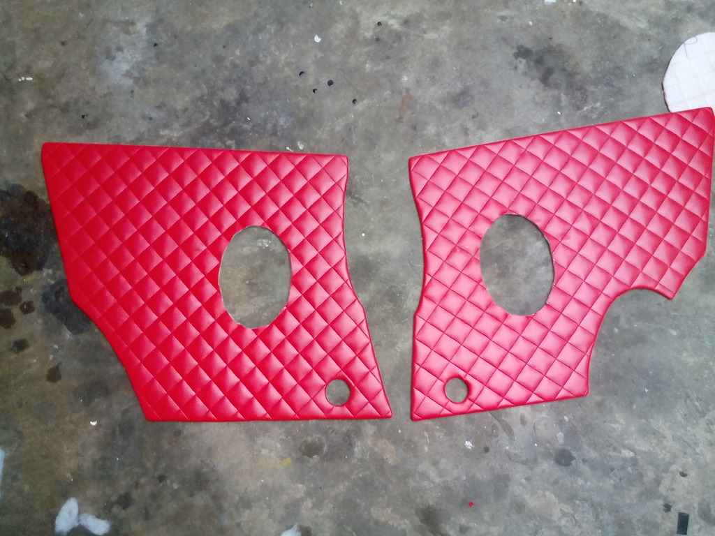 I made some substantial brackets for the speakers which will ultimately be holding the panels on. 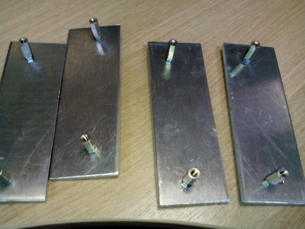 All done I got round to the initial fitting 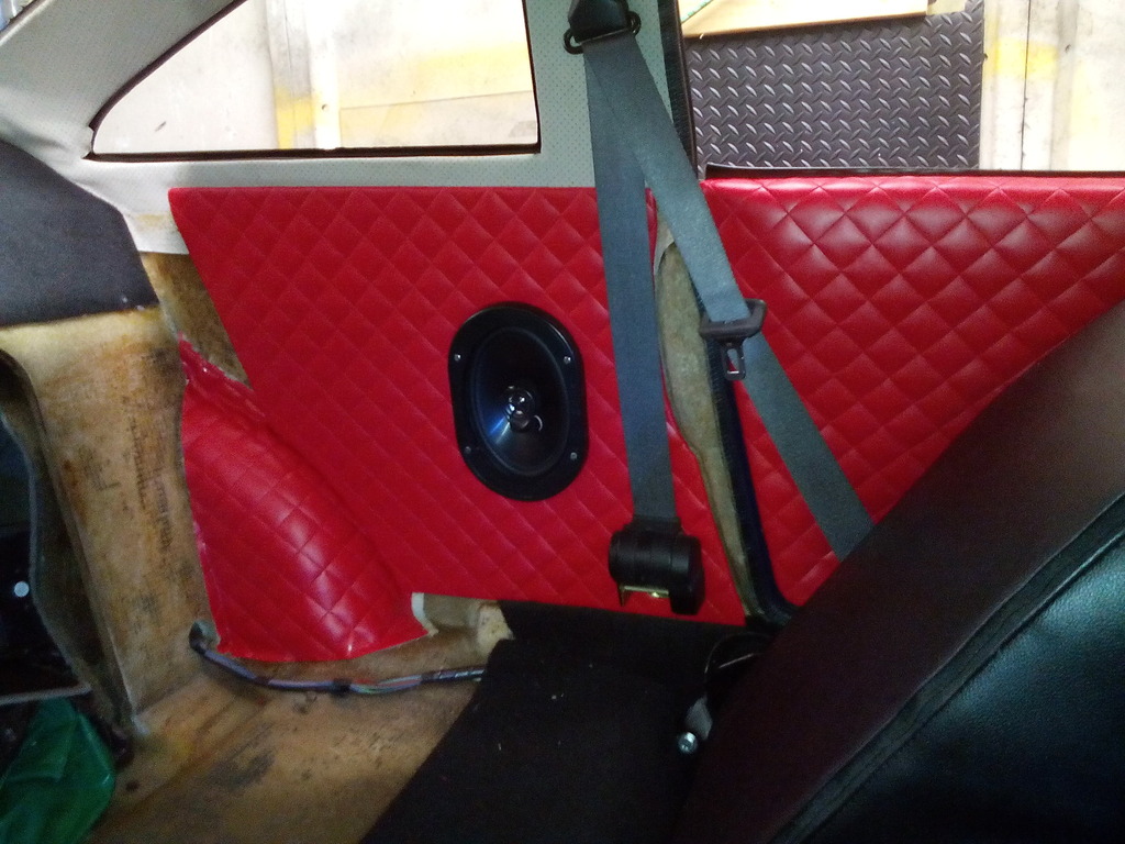 Other side to do plus some extra trimming but alls going to plan, I've ordered another pair of led lights too to aid lighting and further secure the rear of each panel Rear inner panels nearing completion. Firstly some old sloppy glue marks needed removing. 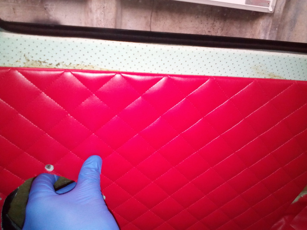 Fin 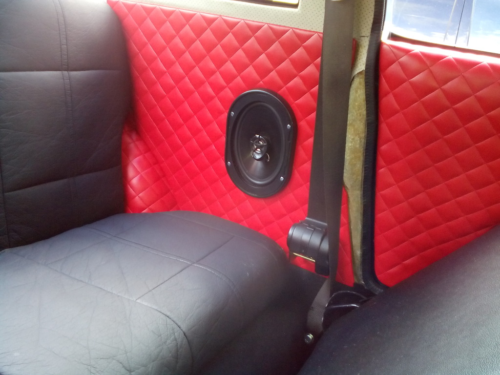 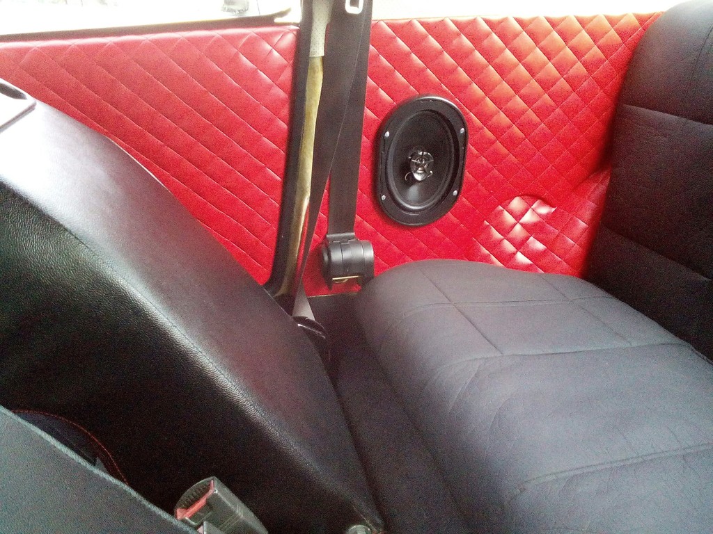 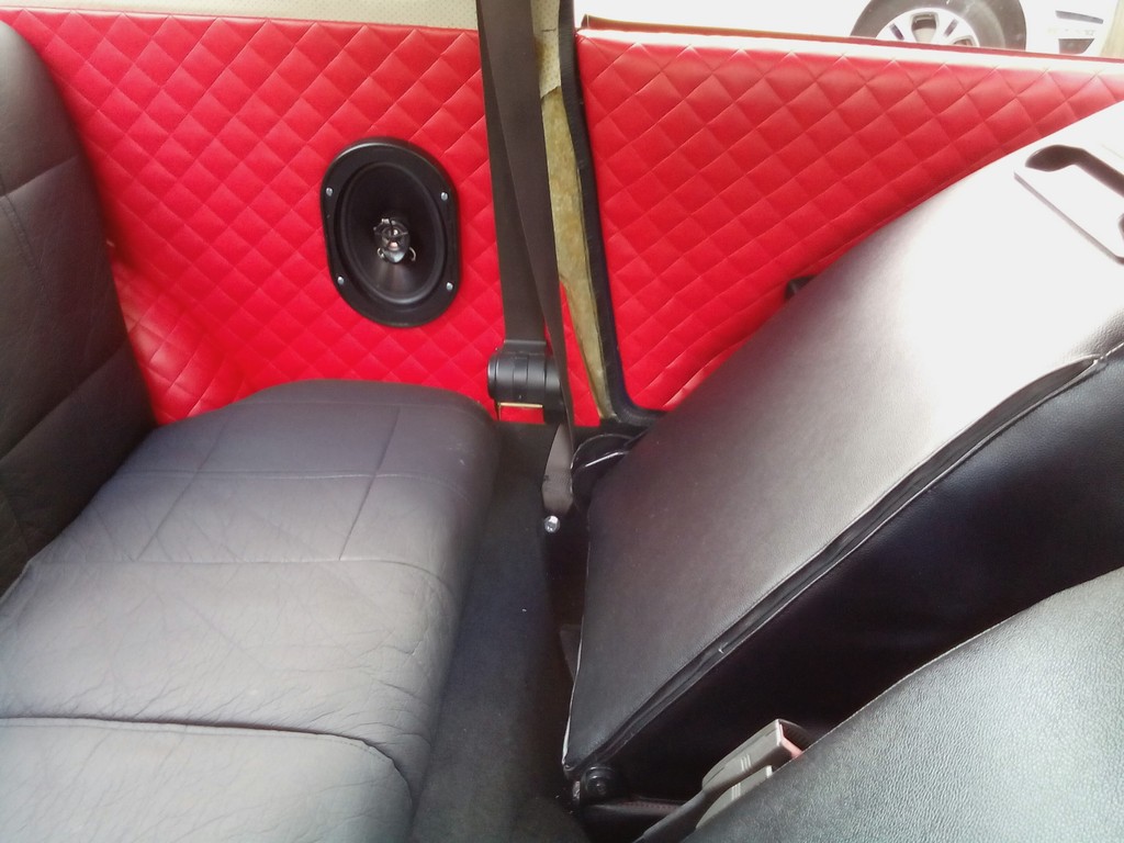 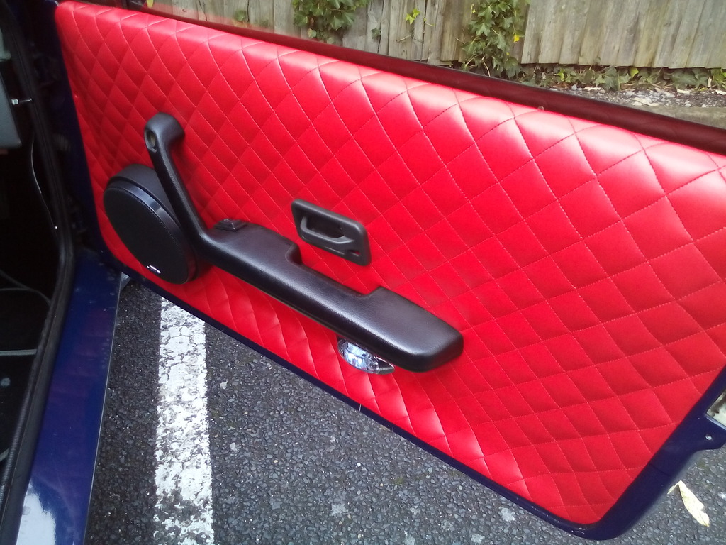 Still the B pillars to do and a few odd jobs but its looking more like a car inside now Edited by Jin 12/11/2015 2:16 PM | ||
| Jin |
| ||
| Regular Posts: 159    | OCT 2015 Upon completion of the door cards and rear panels I set about stripping down the dash 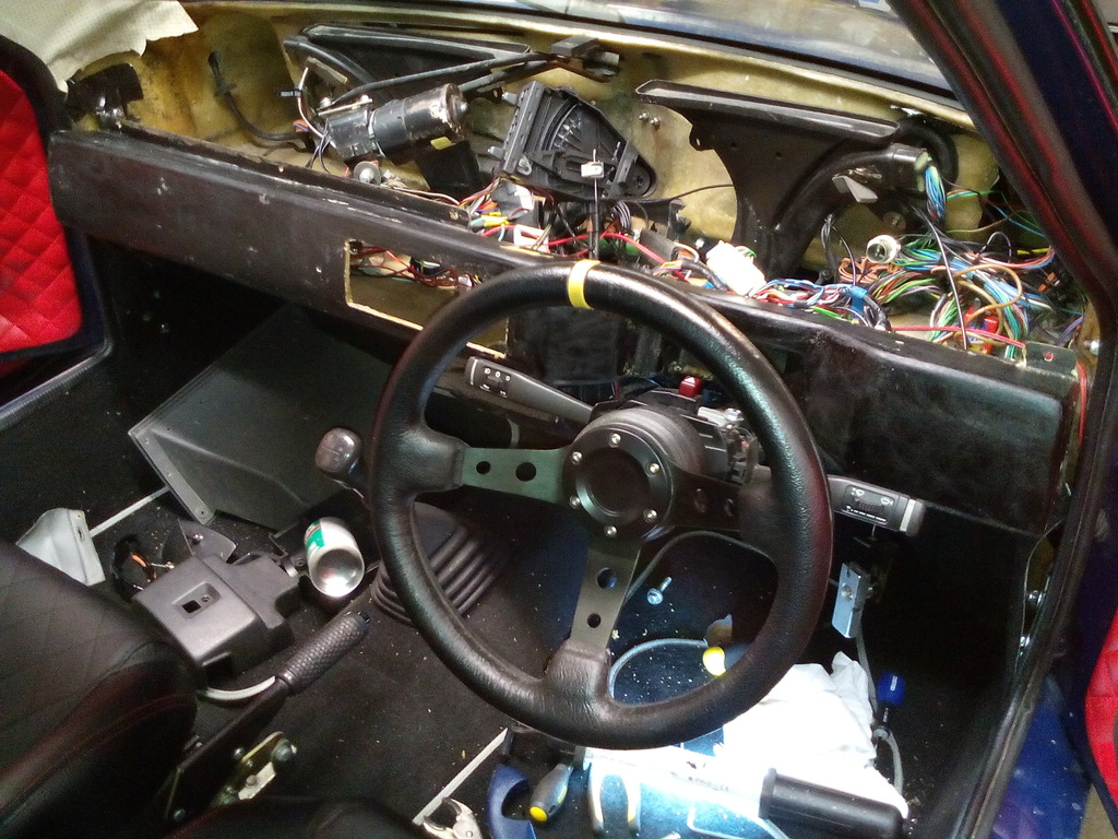 Found yet more dodgy wiring 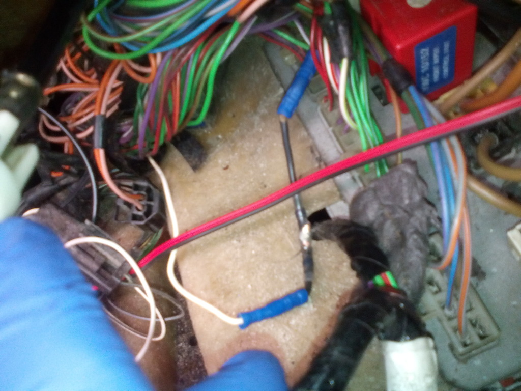 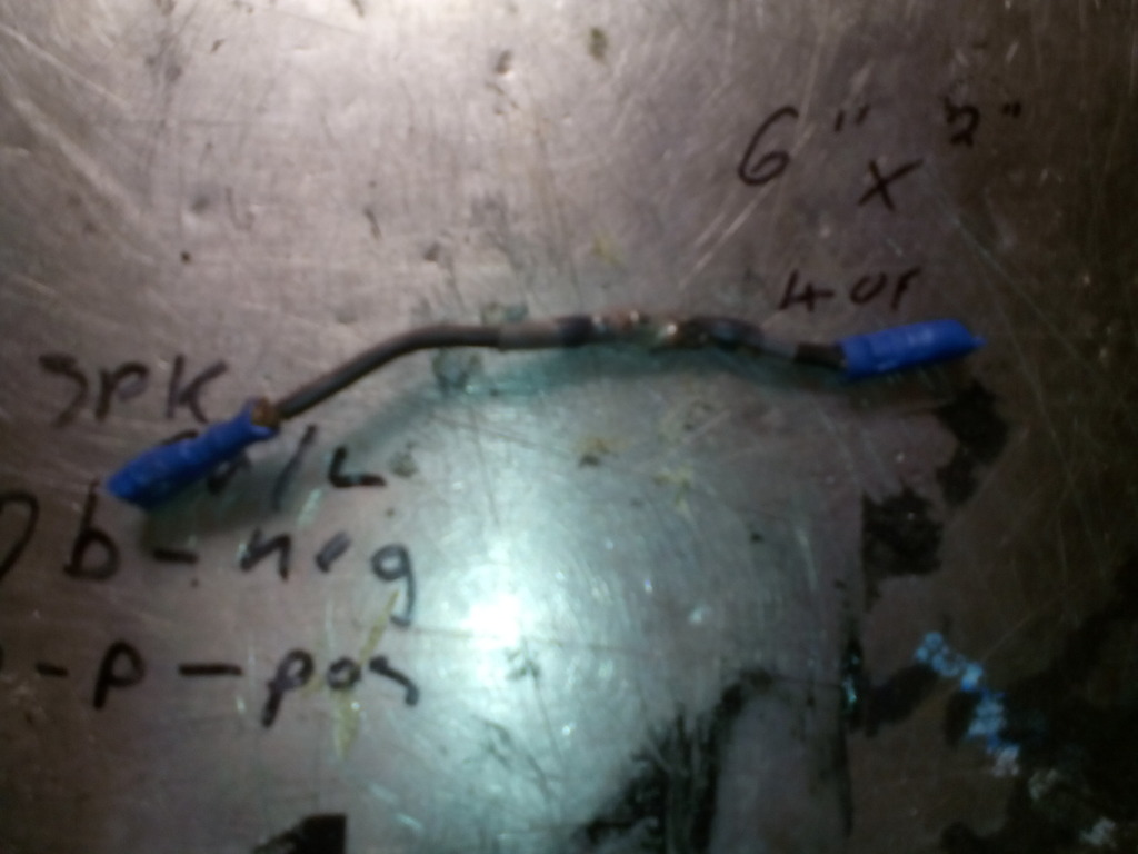 That’s about 3 separate connectors in 2" of cable – surely a record? And digging about by the fuse box revealed more still, it's a wonder this car manages to function, I believes there's black magic involved... 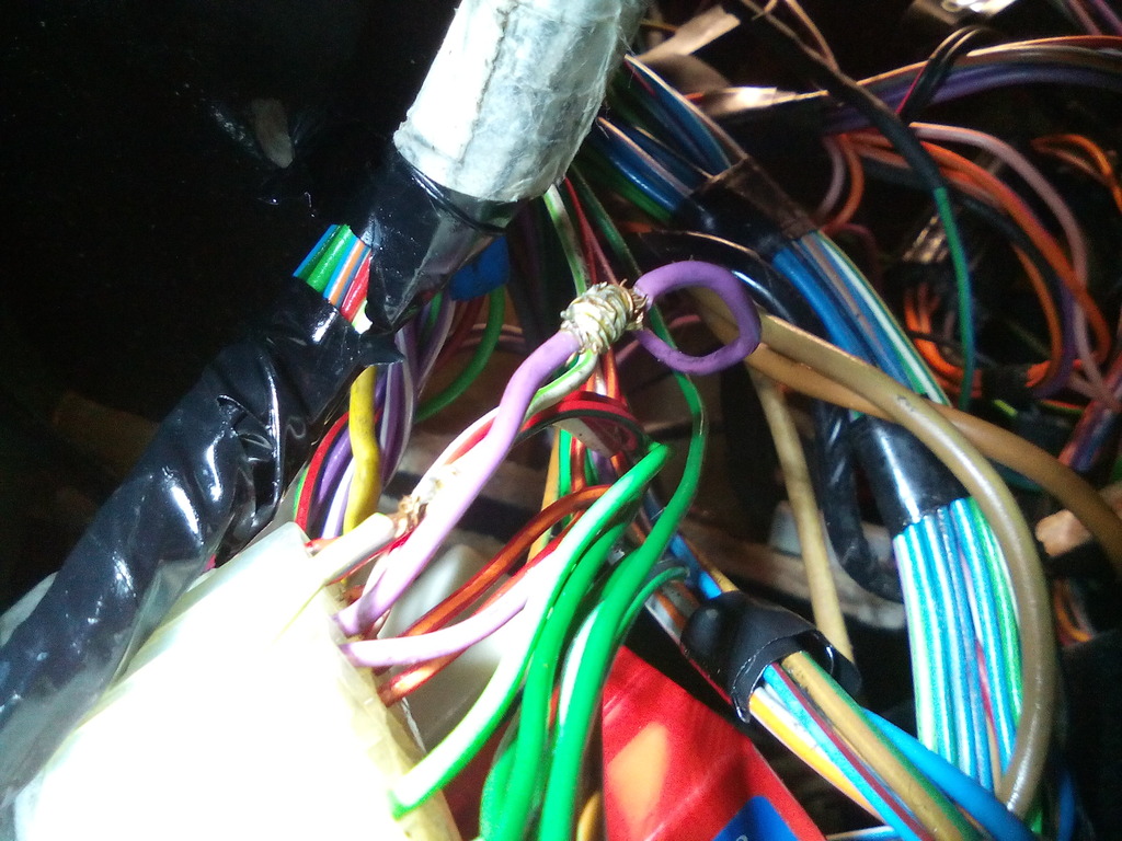 The lower dash got trimmed in matching red vinyl to the doors 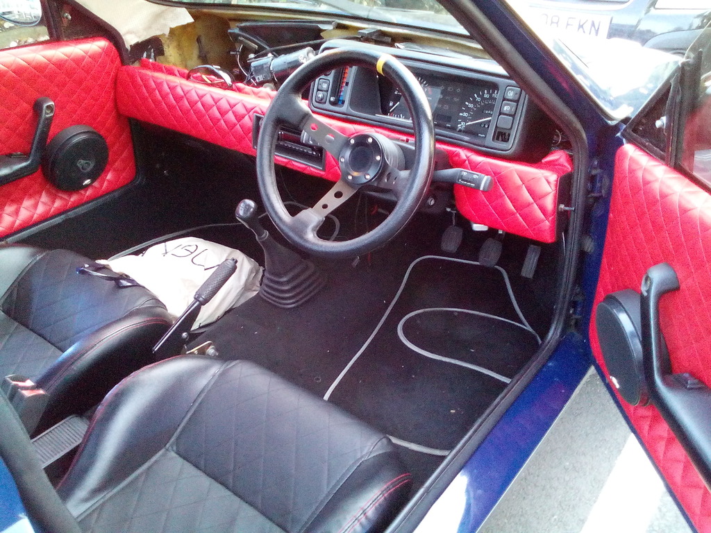 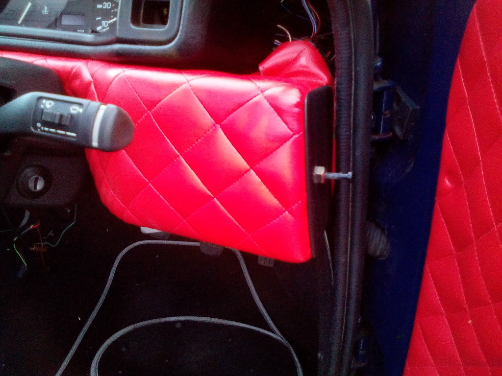 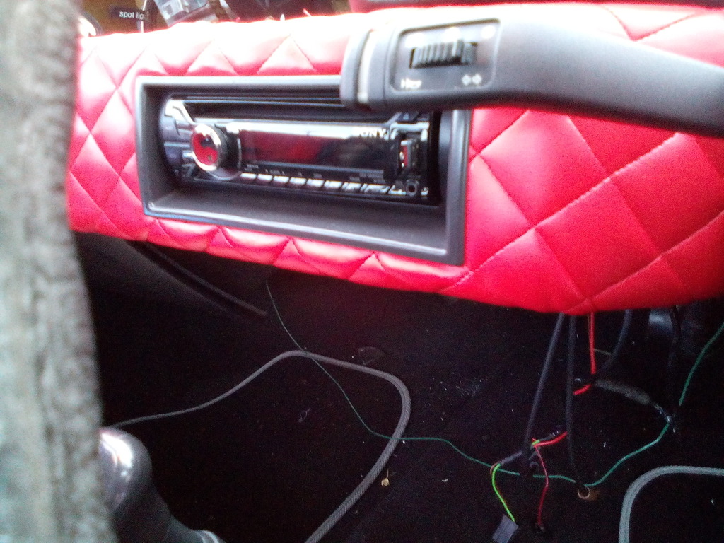 Another Quick fiddle about behind the dash produced this 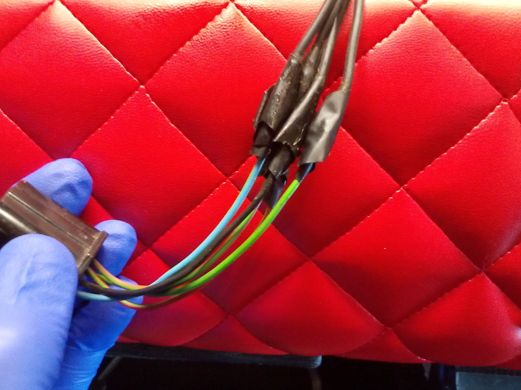 You know when you find wiring like that you’re in for a fun time And it didn’t disappoint 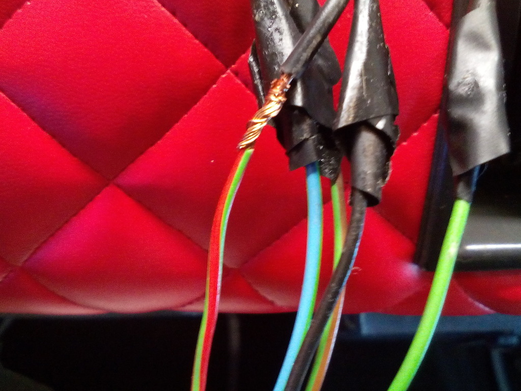 All sorted now though  The glove box and cowl surround didn’t match in with the black / red theme, to be honest the cowl wouldn't match with any themes since it was proper manky, these were re-dyed using VHT vinyl dye- first time I’ve used this stuff but it’s great, looked just as I wanted if a touch glossy. 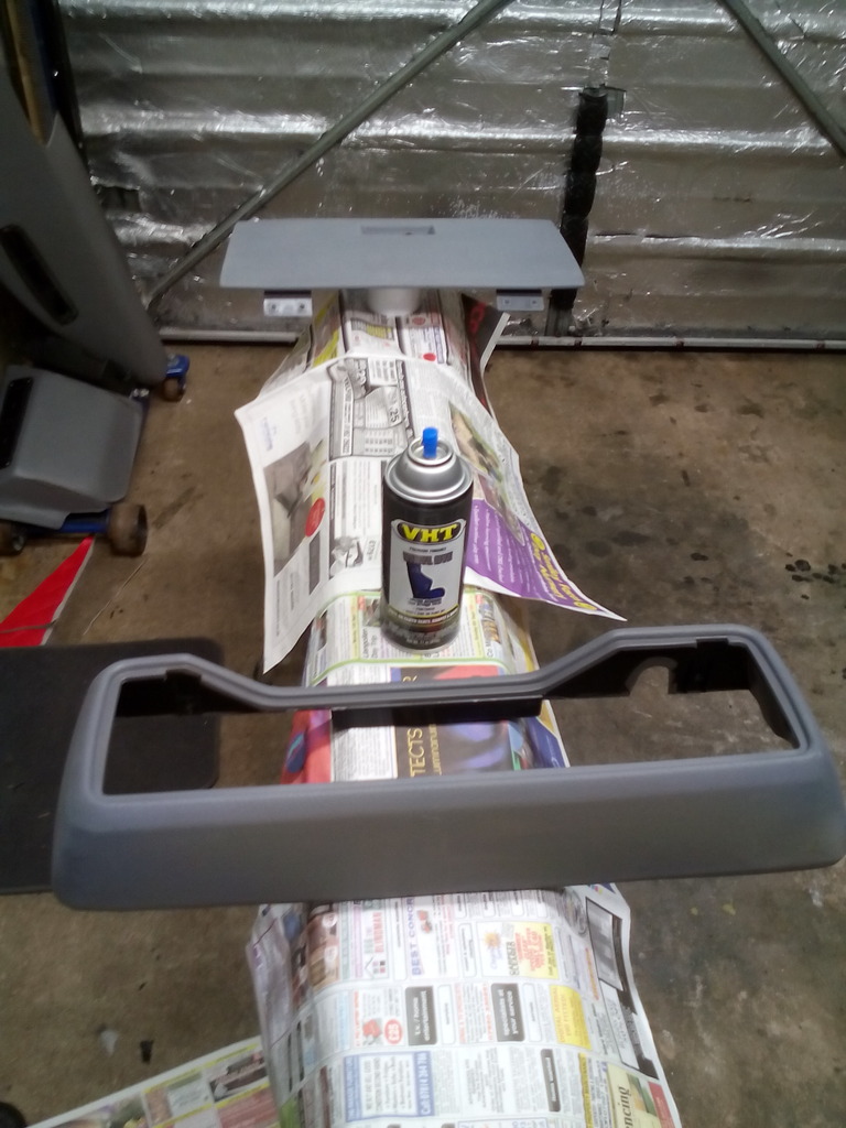 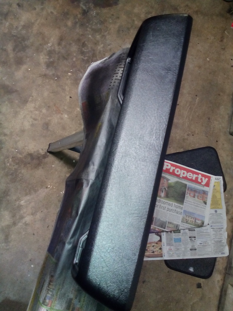 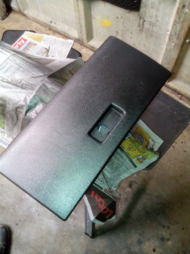 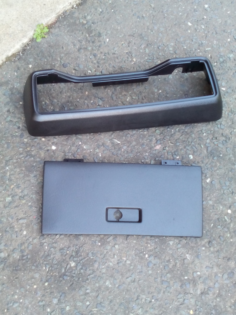 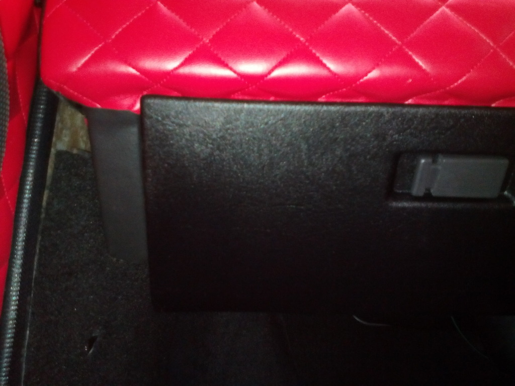 Since I was in the area and one thing leads to another the clocks were stripped down and given a bit of a spruce up, all cleaned and the bulbs swapped for LEDS 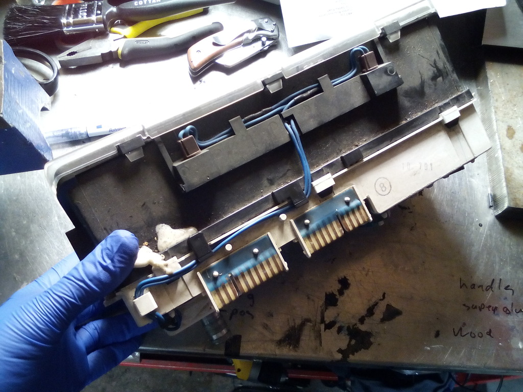 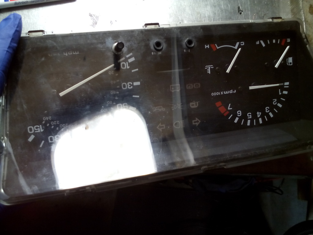 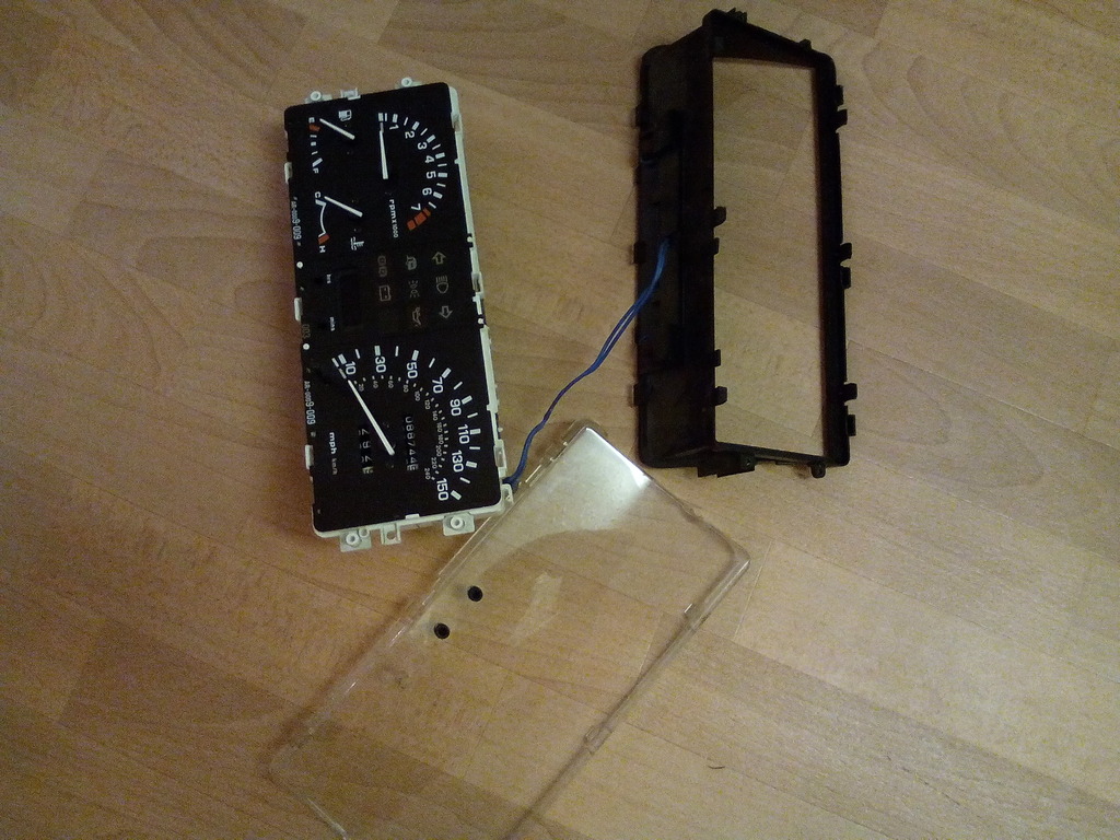 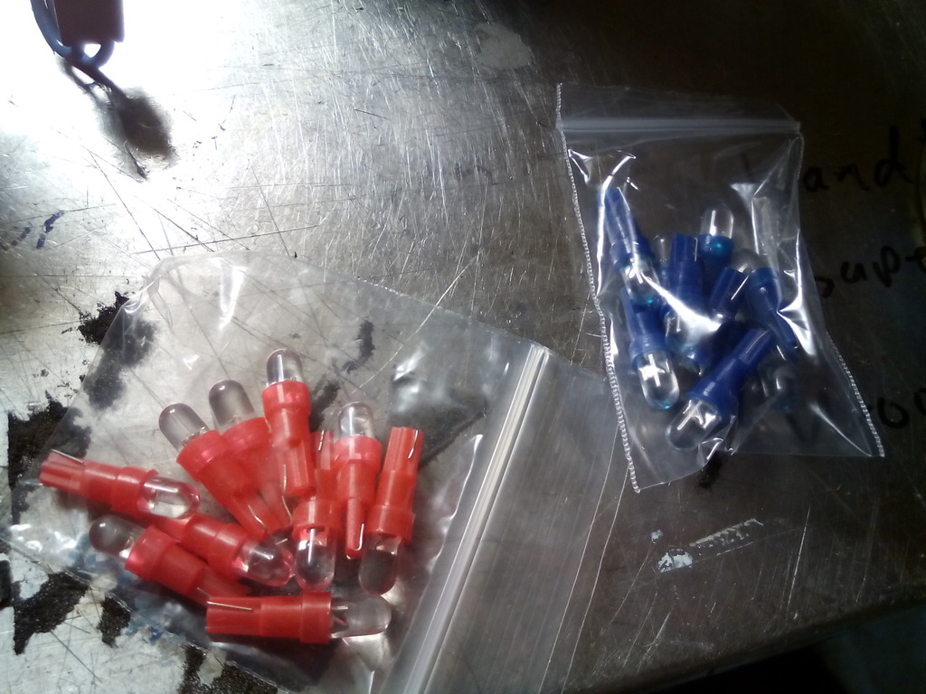 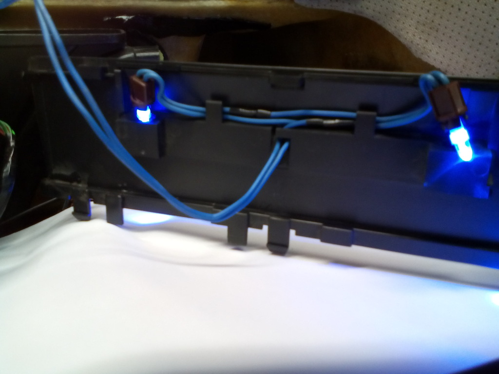 I did try blue and red leds together the theory being the red back illumination would work with the blue front illumination on the needles and produce a nice overall effect, the reality was they both worked against each other and I couldn’t tell what was going on so I opted to go all red - worth it though 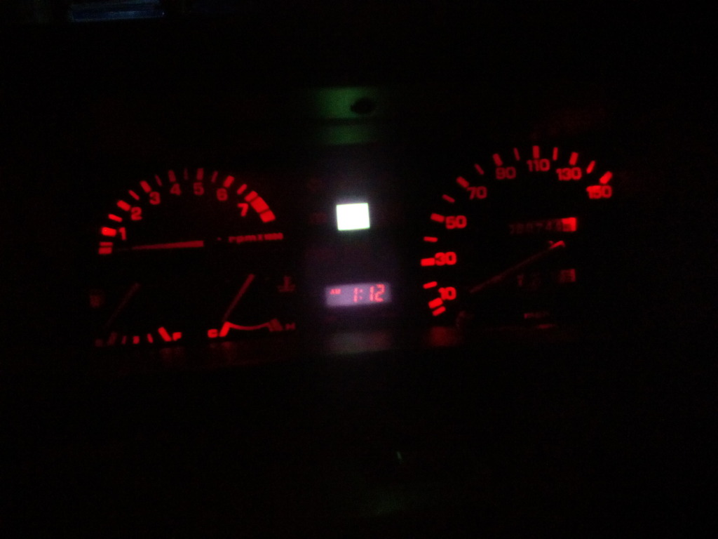 I removed the directional control knob for the heating in preparation of utilising just one outlet from the heater box to divert all air as one to each vent and the flow being controlled by each vent individually – simple but effective, the indicia was blanked with a strip of insulation tape until I can find a more permanent solution, I may fit new controls altogether. 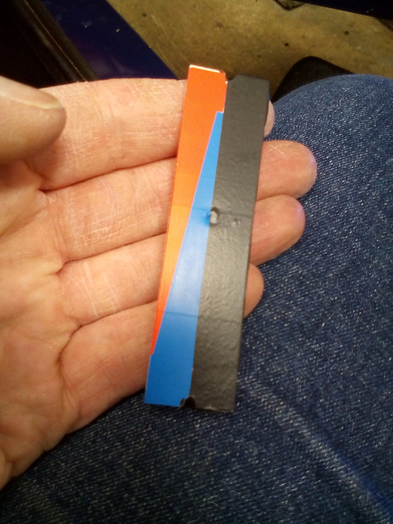 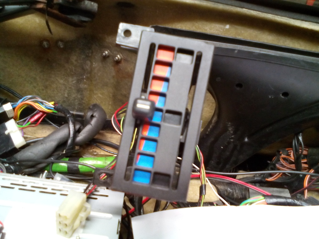 Problems arose when I discovered that the main large outlet from the heater box I intended to use to duct to my new proposed dash and demist vents only blew cold air and this is how they are meant to be? (I would have loved to been a fly on the wall in Rover dealerships back in the day while the salesmen were trying to merit that idea to potential customers) with the only hot and cold air venting to the screen or feet as standard – neither any good to use for all my new dash vents because I needed the extra foot room that was taken up by the ducts for the screen demisters since I caught my foot on them every time I drive the car, you can see the marks on it from me repeatedly catching my foot on it while driving, they had to go.. The centre vent in the lower dash has never worked since I’ve had the car which is not surprising since it was taped over to block the outlet from the heater box and the shonky old fiesta dash vents don’t meet the outlet anyway 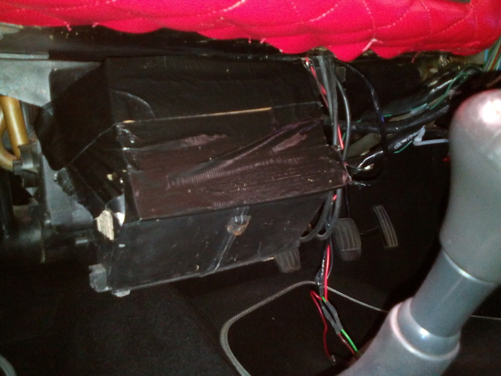 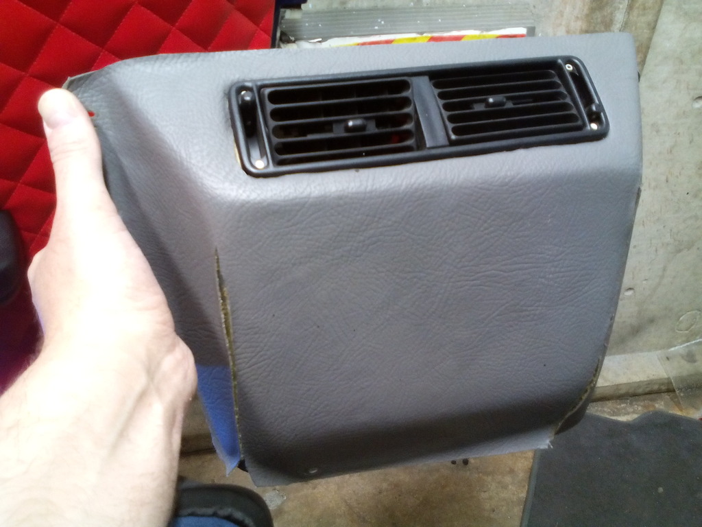 Held in with some sort of pudding 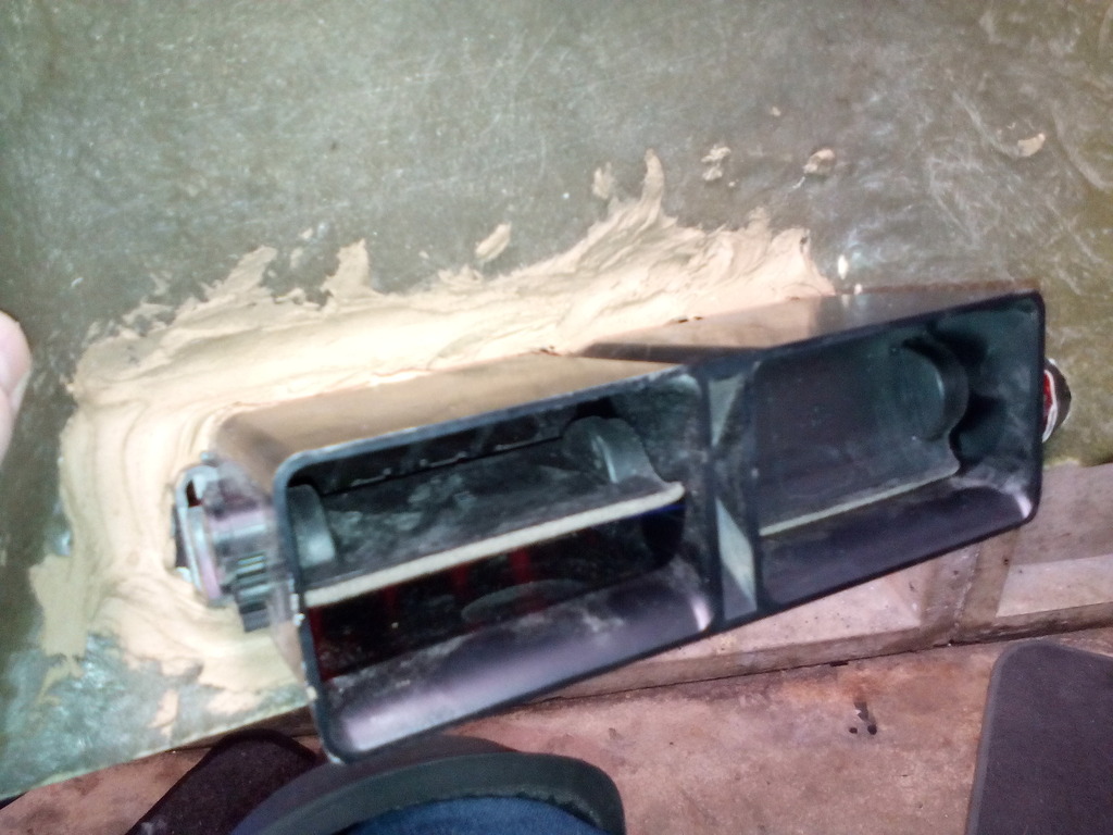 Ripped out ready for re fitment minus shonky fiesta vents 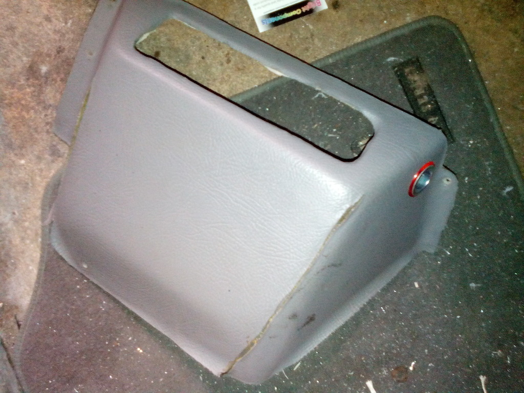 So the only option was to pull the heater box out and rework it to operate as every other car in the world does by blowing hot and cold from all outlets Pulled out 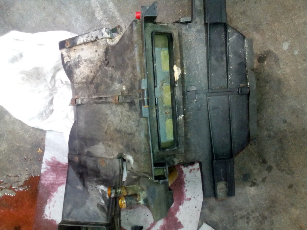 Looked very ropey anyway Stripped down  So now for the reworking.... The rover metro heater matrix uses 3 directional flaps to divert the air where required. 2 operate simultaneously opening and closing together from the hot / cold dash lever, the other controls flow to the demister and feet in that order. Below is a photo of my heater box showing the interior passages and the 2 directional flaps that operate simultaneously   Excuse crummy drawings Cold operation 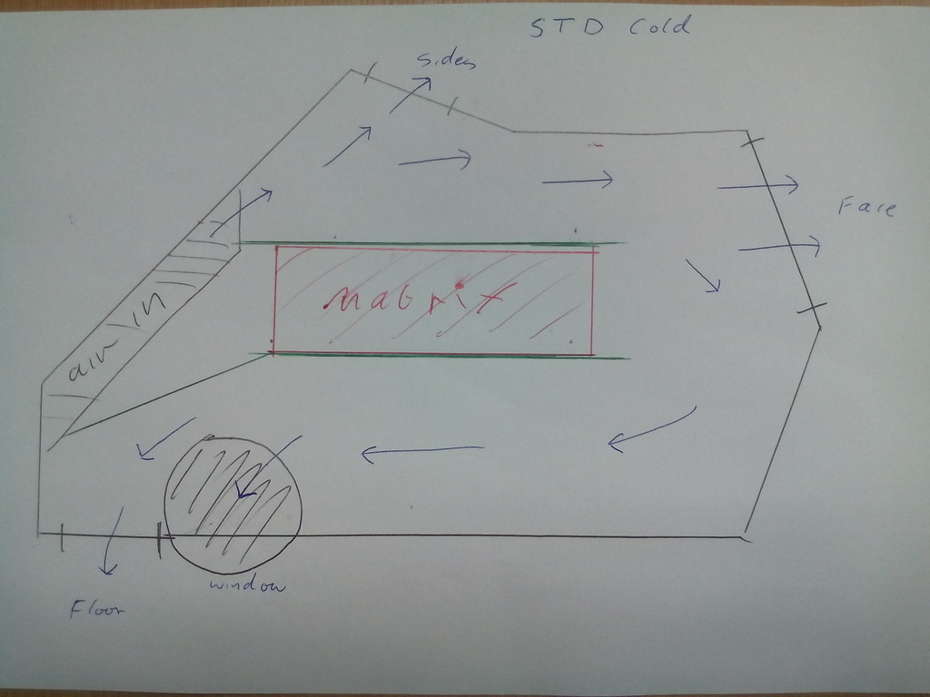 Air passing in from the blower is directed to the open space above the matrix, the closed flaps sandwich the matrix allowing no air to pass through, instead the cold air passed right over the matrix and into the outer section of the heater box where it can pass through the dash vents or with control of the direction lever to the screen and / or feet Hot operation 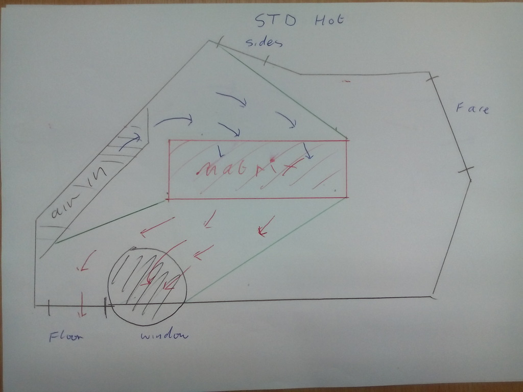 Air passing in from the blower is directed through the matrix via the upper directional flap, the hot air cannot enter the outer section of the heater box due to the lower directional flap closing this area off, instead the hot air is diverted to just the lower section of the heater box where it can pass through to the screen and / or feet Modification Cold operation  By removing the lower directional flap that covers the lower section of the matrix (the outlet if you like) the cold air can flow in exactly the same manner as before, no air is passing through the matrix so none is heated, the cold air can still be diverted also with control of the direction lever to the screen and / or feet as well as the face exactly as before. Hot operation  With the lower directional flap that covers the lower section of the matrix removed and the dash control lever turner to HOT the upper directional flap opens allowing the cold air to pass through the matrix to be heated, the hot air now enters the outer section of the heater box where it can now pass through the dash vents or with control of the direction lever to the screen and / or feet, (I have shown the direction control flap closed but this still operates to blow hot air at the screen and/ or feet even with the dash vents open and you can meter how much flow is diverted through each outlet via the dash levers to produce an even flow through each if required. All of that is irrelevant though since I’m only going to use the large main centre outlet for all my ducting, more on that soon... I took a bit of time cleaning everything and replacing the foam seal because they were manky and the end result is a fully functioning air box that blows hot and cold to all outlets The 2 flaps to be refitted  Some of the old outlets from the heater box were blocked off with bits of wood originally so these that were never going to be used again had tight fitting gaskets made from closed cell foam to block each off   All the controller flaps were re trimmed in foam vinyl off cuts since these give just the right amount of seal.    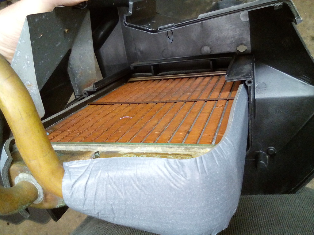  All built back up I ripped out the blower motor also and pulled that apart and gave it a damn good cleaning 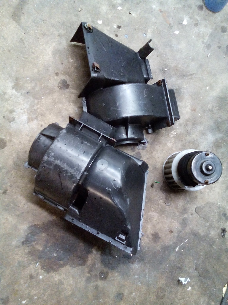 The metal mounting plate for this on the bulkhead leaked like a sieve and looked sorry for itself 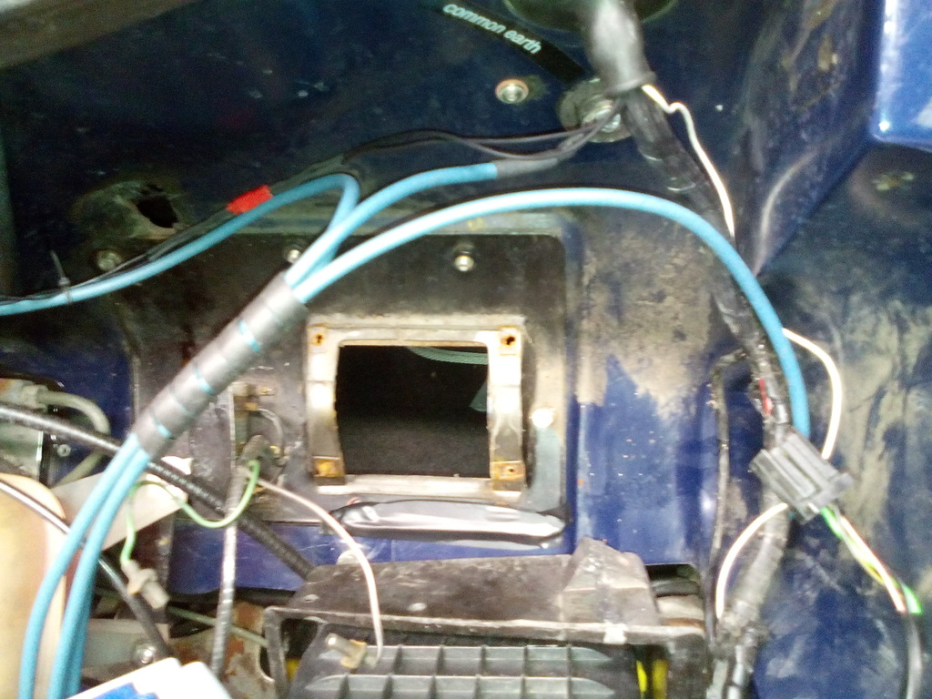 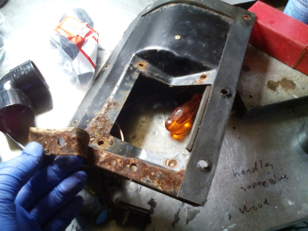 Blasted 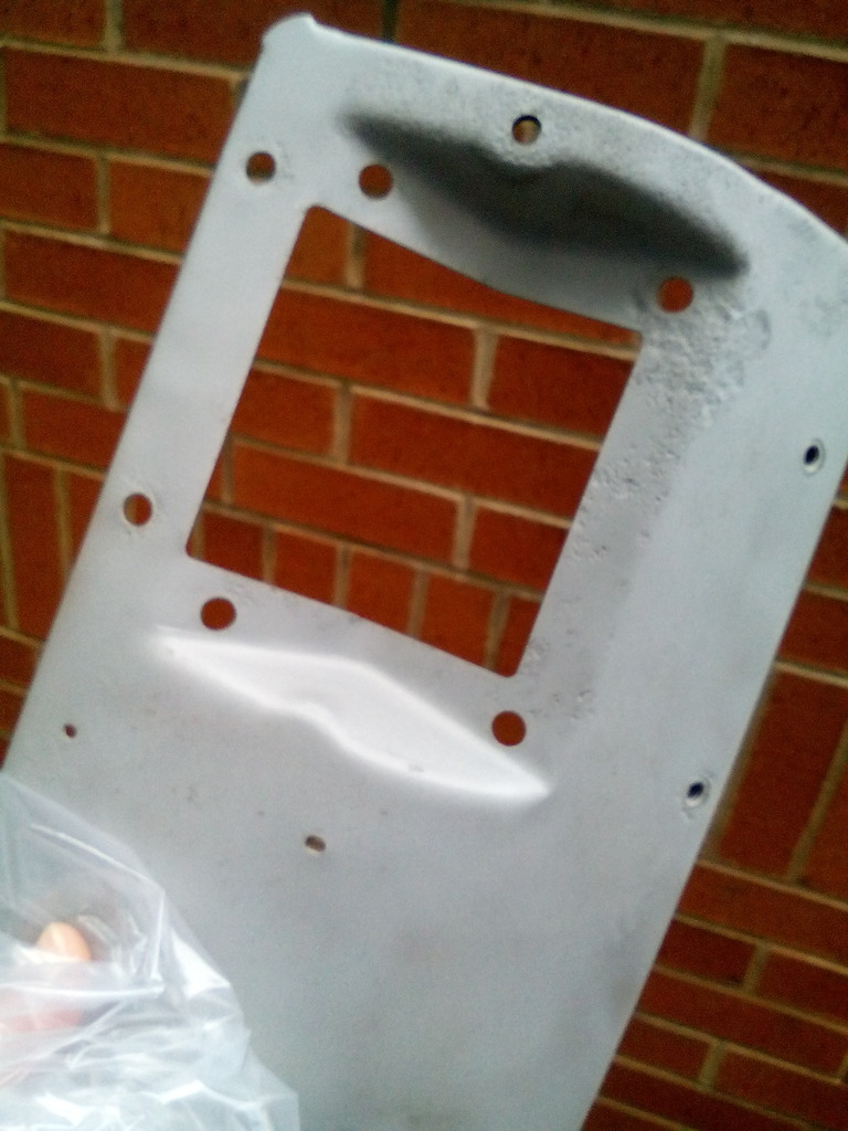 Painted 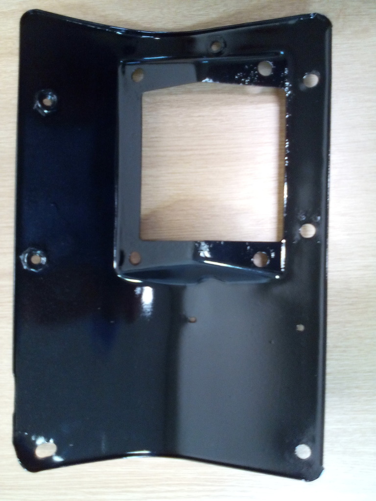 All good but now I’m going to have to do the driver’s side clutch / brake plate to match Once Fitted I noticed the wiring that ran behind the blower motor was starting to chafe so that got the spiral wrap treatment 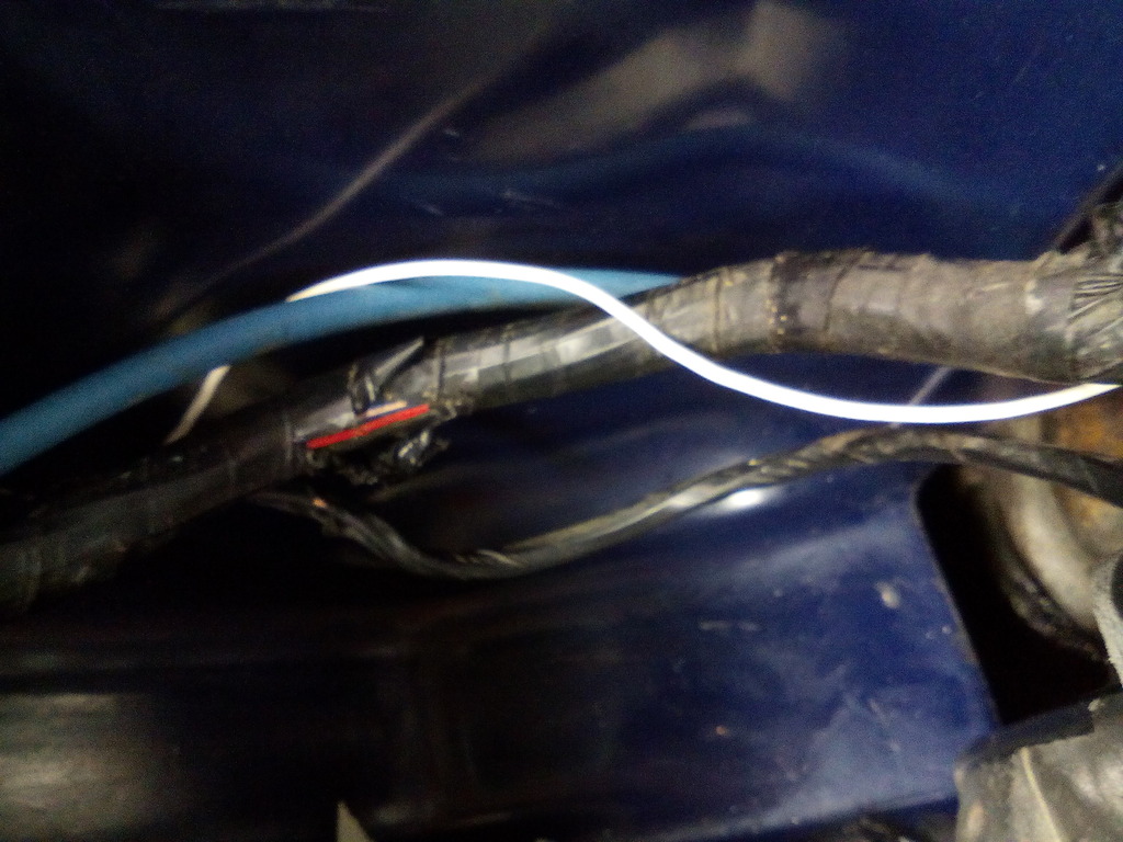 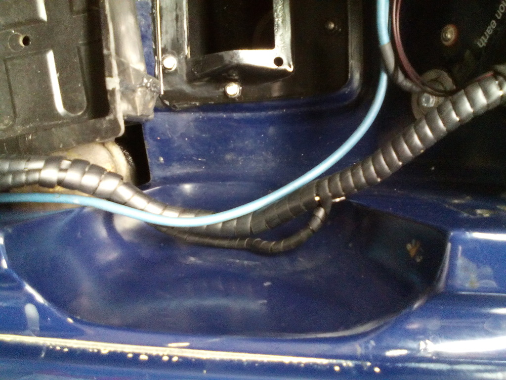 Upon refitting the heater assembly I even made a new foam gasket for the matrix pipes 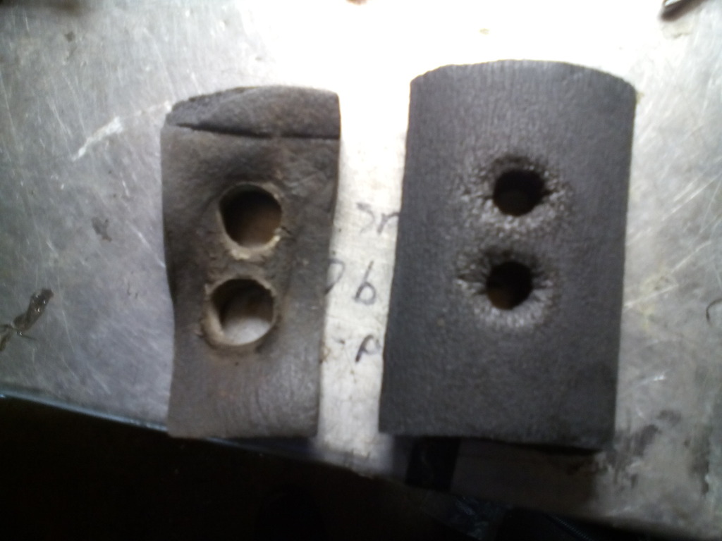 regarding the sealing of the heater box - bulkhead plate - blower motor, rather than make sponge gaskets for the joins as originally done I set the freshly painted bulkhead plate in with non-setting screen sealant, the benefit is total water tight seal and less chance of rusting again. Once fitted up I turned my attention to the blower motor resistors, the heater has only ever worked on flat out indicating the load resistors are passed their best, so rather than trying to hunt down some replacements (hens teeth) and have them fail in time, I made some new ones out of ceramic hi power resistors mounted on a custom aluminium heatsink 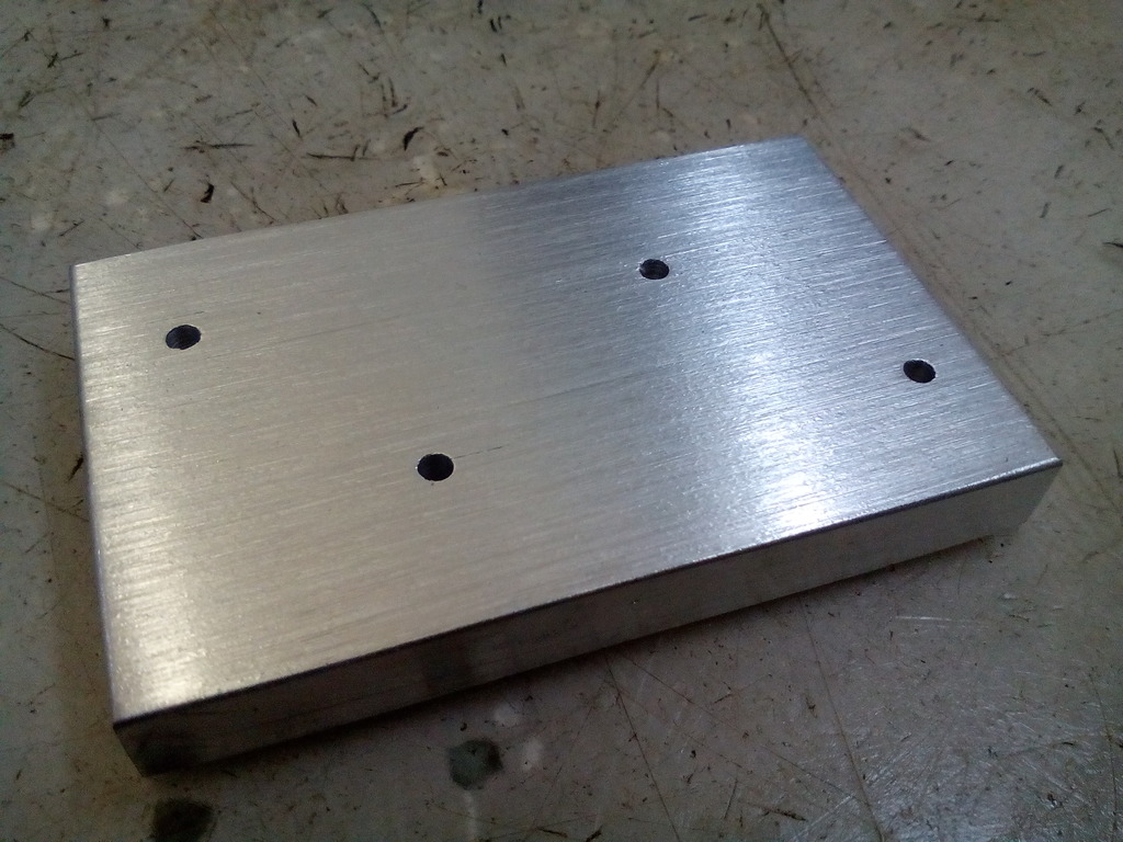 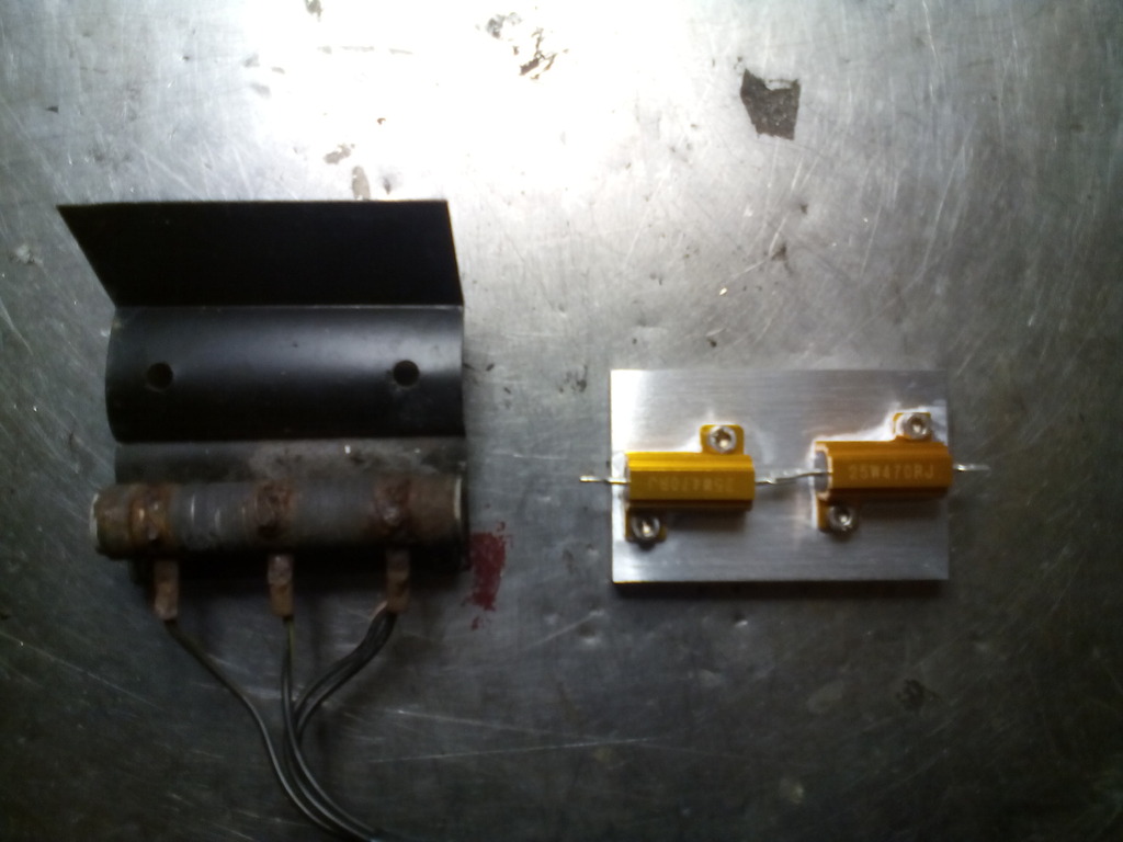 Much better and nice to look at too So now I’ve overhauled the entire heating system I’m back to where I was a month ago where I needed to start making ducting to the various positions on the dash for my new vents which I’ve still yet to order..... More on that as it progresses Alongside the dash I acquired some new headlights mentioned previously, the old ones doubled up as fish tanks 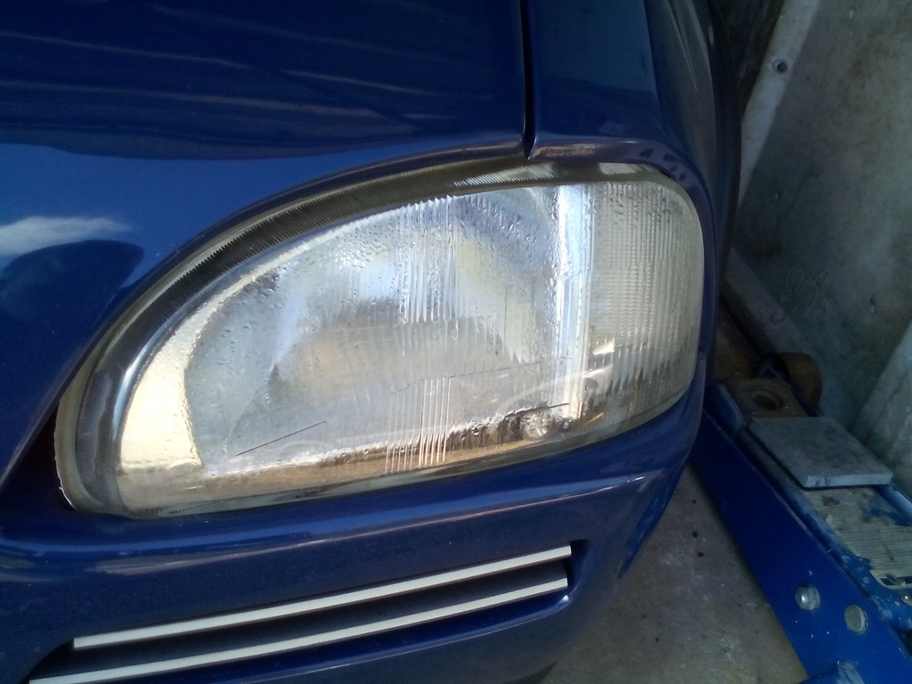 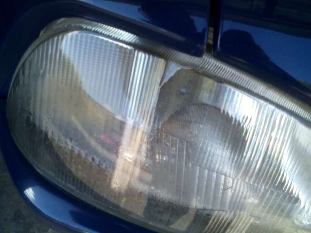 I didn’t just want to fit the new ones and be done with it, the front end has always looked a bit awkward and the rover 100 headlights aren’t the most manly looking so I decided to tint them – trying to find the right tint was harder than I expected, in total I bought 8 different types to try, half were so subtle (despite being called medium) they just made the lenses look grubby and dull – a bit like they did before so not much point, the other half of the tints I bought were so dark they could have passed as blackout blinds, only by chance did I locate a company that put actual pictures of their products on their website could I find the perfect tint – just enough but not too dark Didn’t trust myself to do the work so I got a local tinting company to do it for me (last thing I needed was for them to look like a badly presented bag of chips) They did a cracking job too, only gripe was they left the bottom bare because of the sharp rebate, this was out of sight anyway but it felt a bit unfinished so I got around this by buying some black glass primer and painting it In, the black served to enhance the darkness of the tint by refracting the black around the inside of the lens yet not effecting light transition performance – sort of like how live edge plastic works but in reverse. 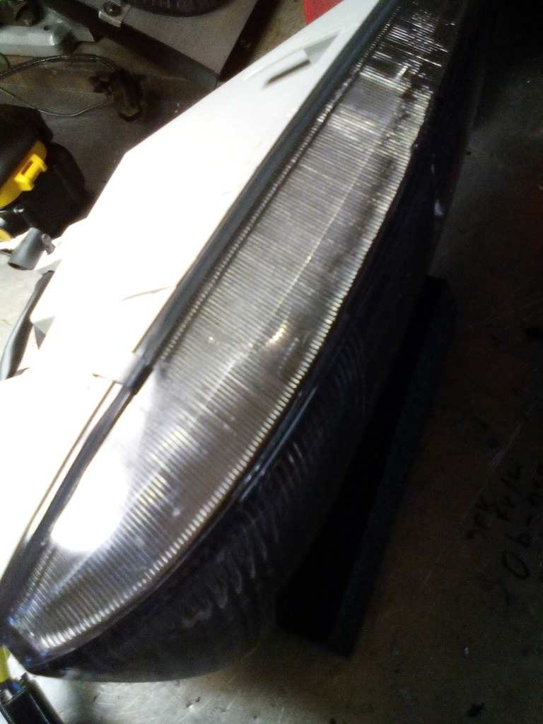 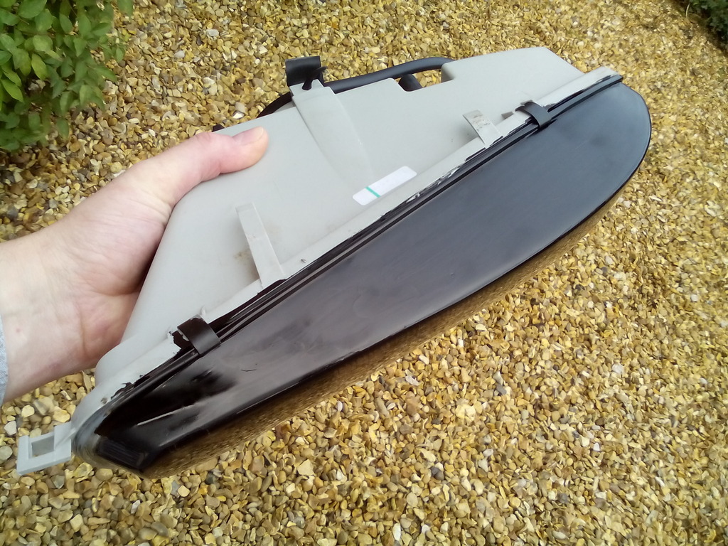 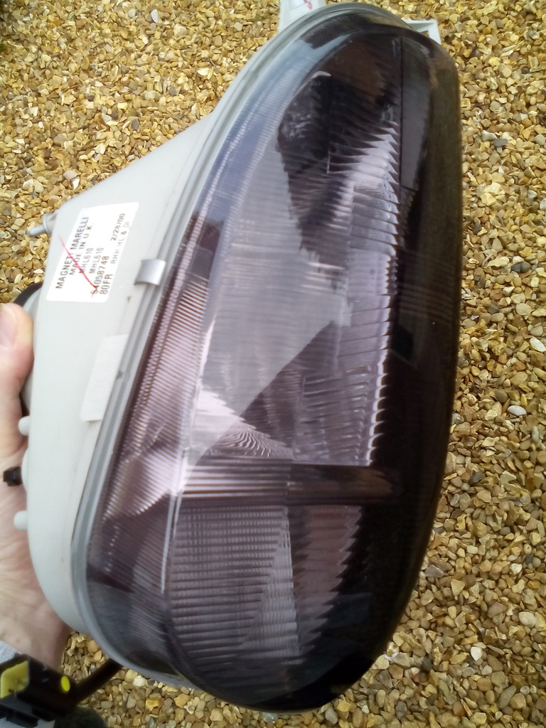 Splashed out some new bulbs too 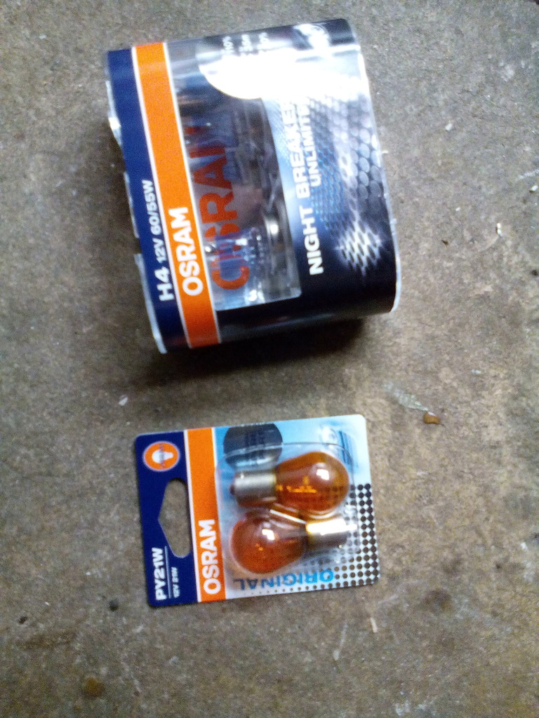 All fitted 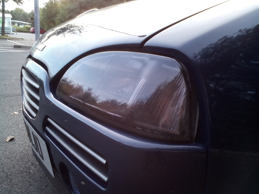 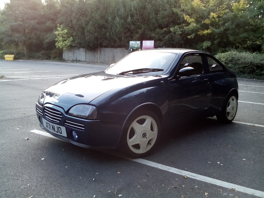 And tired of losing my nuts inside the inner wings (ouch) each time I undo the headlights I swapped the nut and bolt arrangement 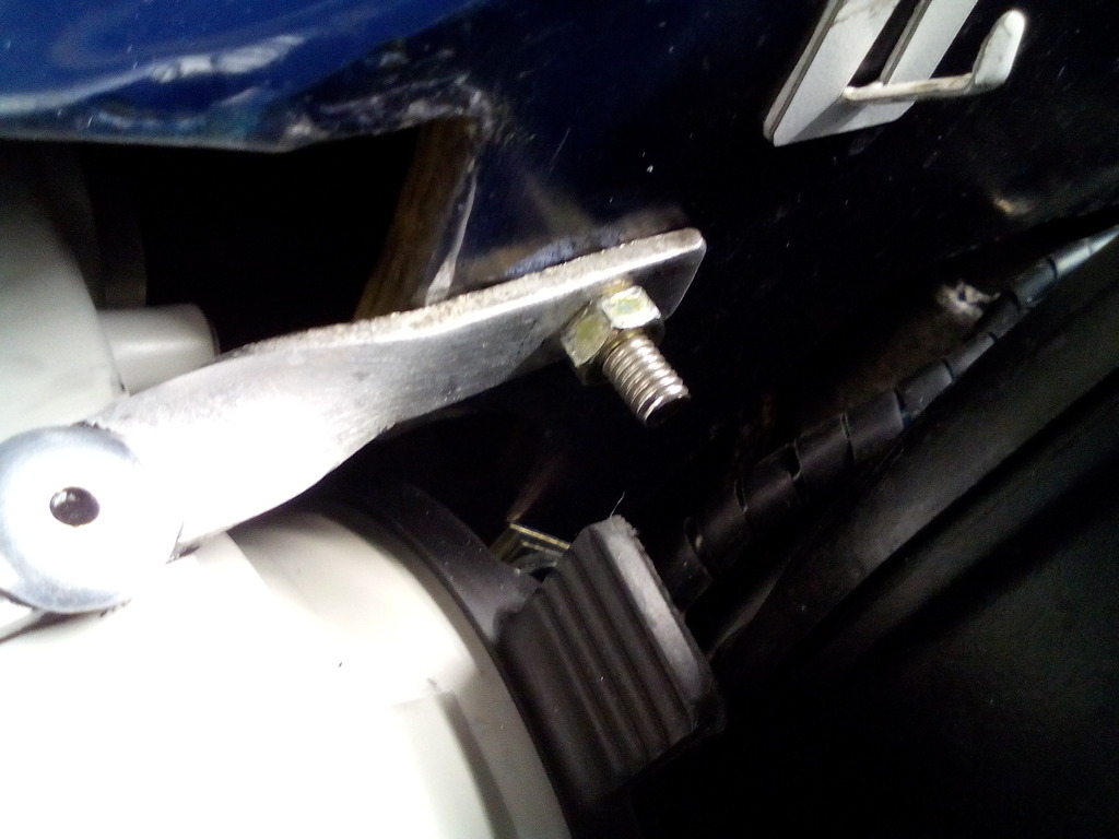 By making up some alloy captive nuts and bonding them to the rear of the fixing so now it's all taken care of from the front 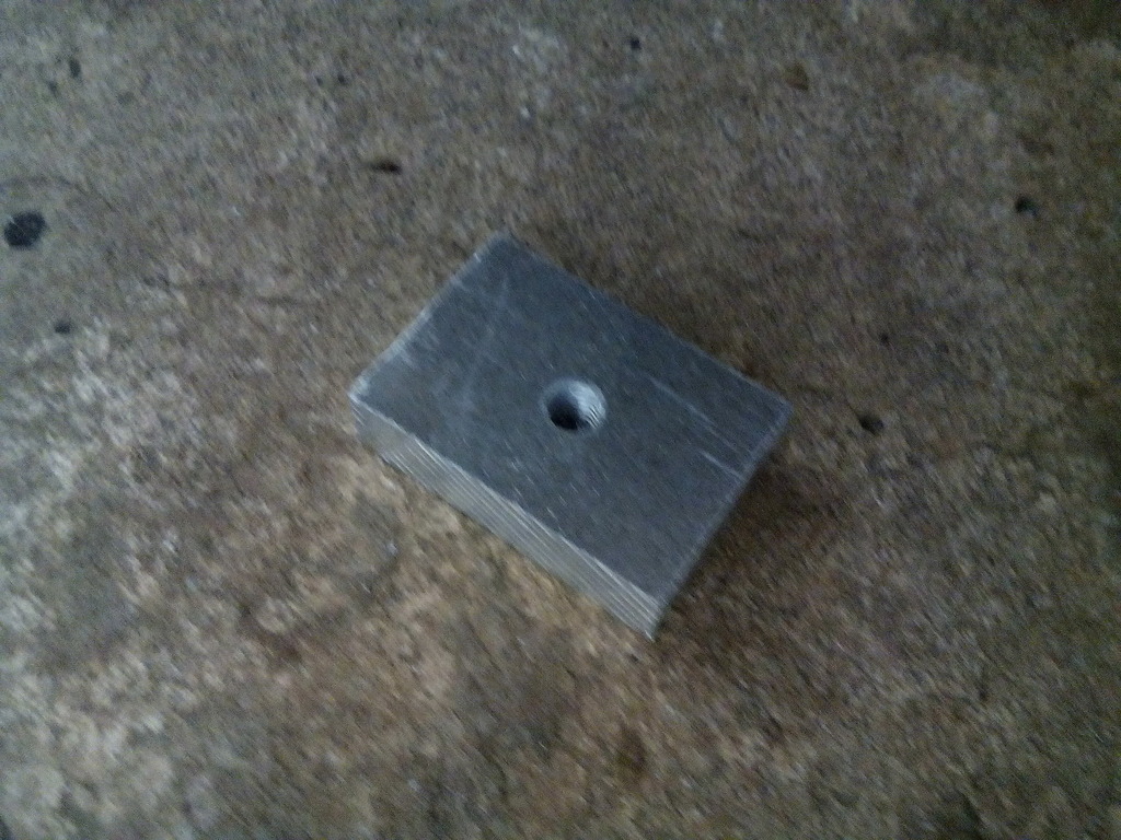 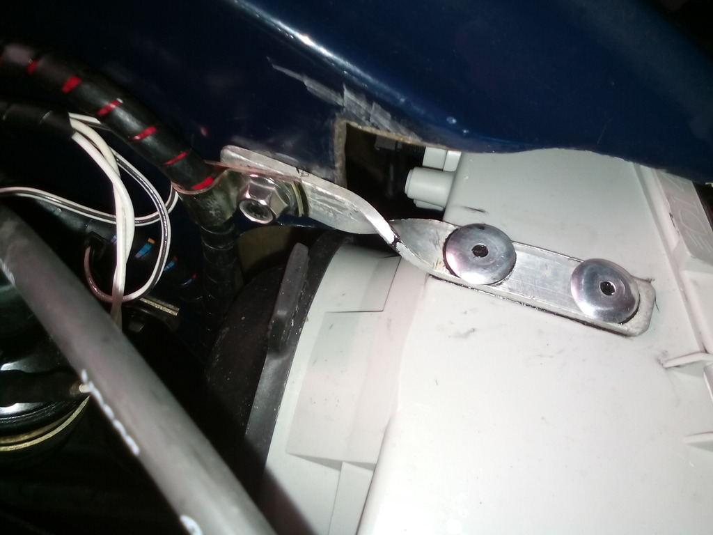 Before anyone questions the darkness, the actual tint is half as dark as you see in the photos and that is what the bulbs have to shine though, the tinted effect to the eyes is twofold since the daylight passed through the lens once then reflects off the reflector and back through the lens before it hits your eyes giving x2 tint whereas the bulbs just pass once, I can say that with the new bulbs, new reflectors that despite the tint the lights are much brighter than before, just got to make a new trim to go round the edge. thanks for reading, this brings us up to the present day with more to come | ||
| Tobys |
| ||
 Regular Posts: 179     Location: Sittingbourne, Kent | Wow what an amazing build, so much attention on detail, it looks the part mate that's for sure! I've never seen one of these before, but looks amazing! Nice build! | ||
| Jin |
| ||
| Regular Posts: 159    | Thanks mate. , you don’t see them often they are a bit few and far between, and the looks have grown on me over the years especially since I first saw one on the cover of “which kit?” magazine when i was 15 years old and i thought it was fugly then and still do to a degree now, never thought in a million years i would end up owning that exact car. Still loads to do on it, mostly cosmetic such as afterburner tail lights and skirts etc. and engine swap and replace hydragas to coilovers etc. ill post up here as i progress Cheers  ($T2eC16dHJGQE9noMbT+KBRPd(zt8-g~~60_35.jpg) Attachments ----------------  $T2eC16dHJGQE9noMbT+KBRPd(zt8-g~~60_35.jpg (31KB - 115 downloads) $T2eC16dHJGQE9noMbT+KBRPd(zt8-g~~60_35.jpg (31KB - 115 downloads) | ||
| Jin |
| ||
| Regular Posts: 159    | Bought a brand new thermostat housing and upgraded 82 deg stat due to a slight weep from the old housing and the standard rover stat being a total bu££er to bleed, It still is a total bu££er to bleed but in a less obvious way which is progress of sorts 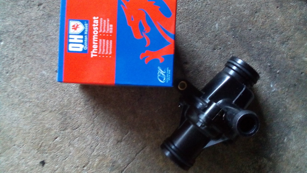 | ||
| Jin |
| ||
| Regular Posts: 159    | Whilst improving the cooling system, and still trying to bleed the remaining bleeding air out the system I set about making a bleed pipe for the matrix top hose. 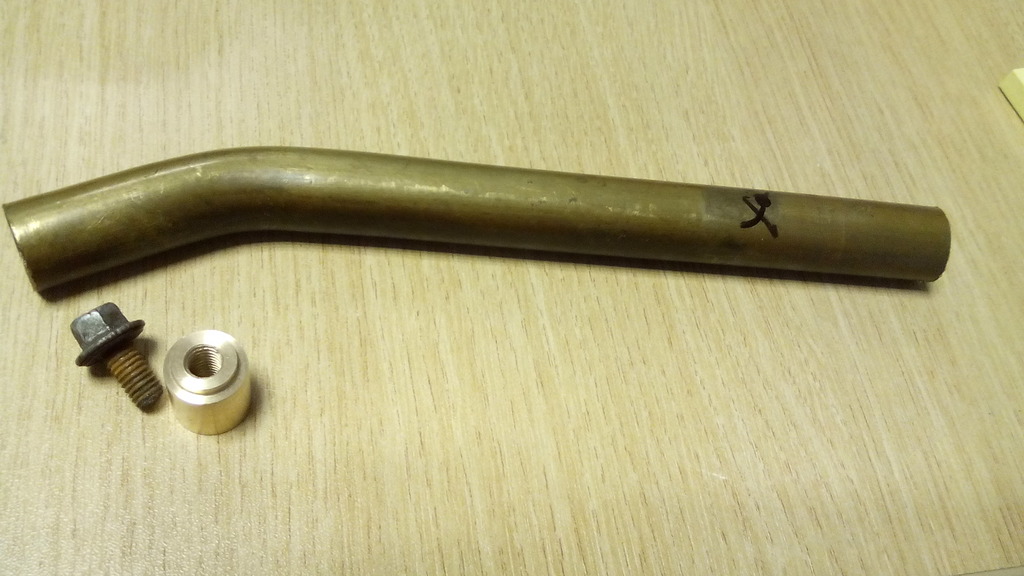 Off cut of brass pipe, turned up a threaded boss also in brass and reused the bleed screw from my old rear coolant pipe, 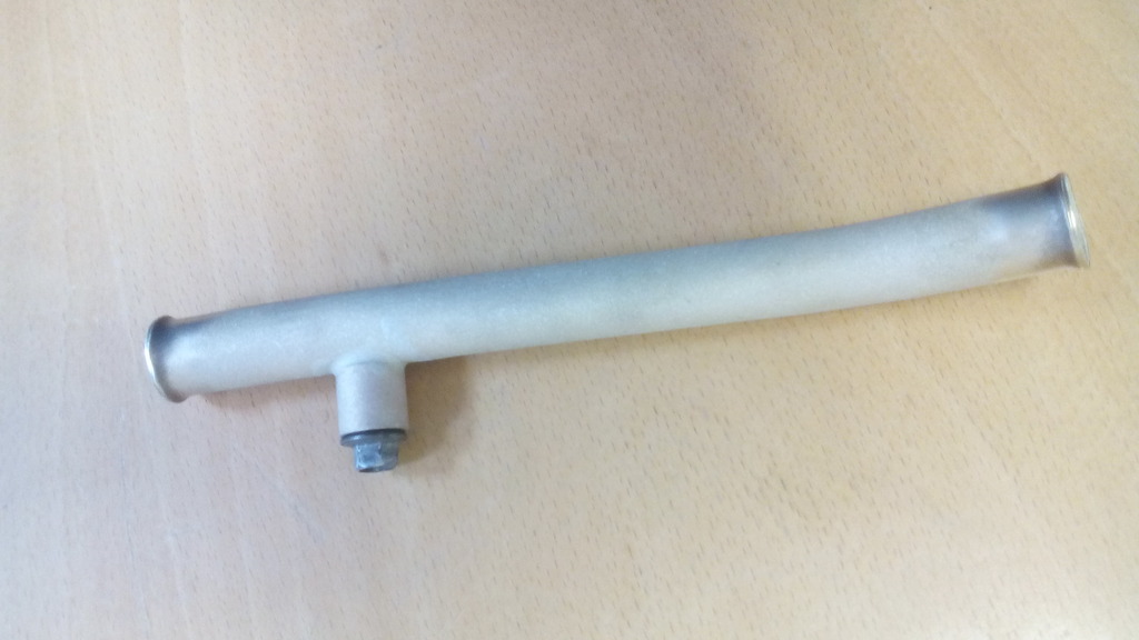 Made up a stainless support 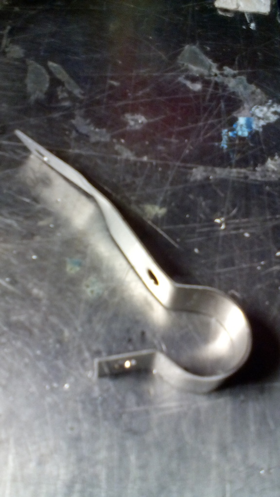 Painted and fitted 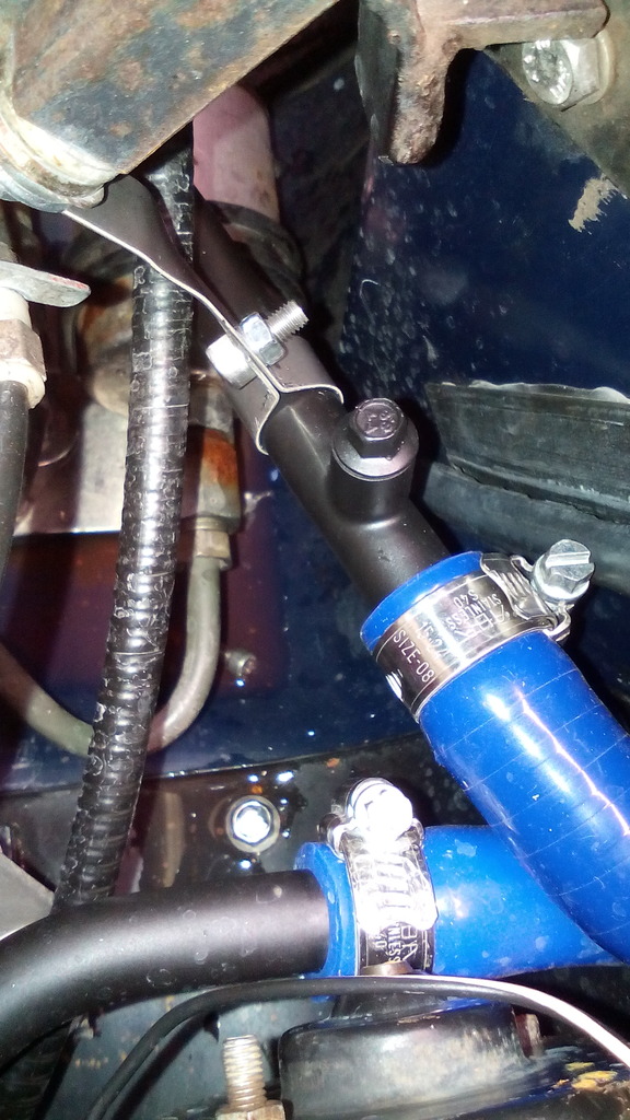 Seems to work | ||
| Jin |
| ||
| Regular Posts: 159    | The problem with my current scuttle panel is although it looks nice, it's just a ledge that allows water from the screen to pour in and fill the bulkhead ledge and pours all over the fan motor invariably giving it excuses to play up 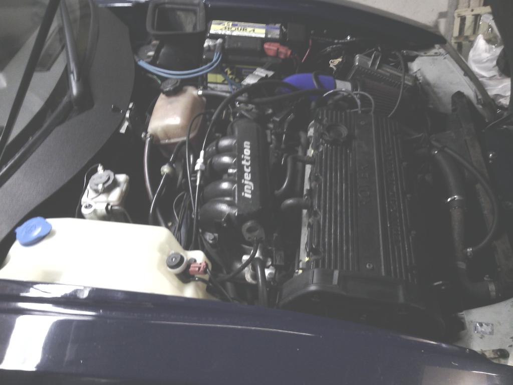 Also, back when I made it I just coppied the shape from the original one including the big cutout for the wiper arm 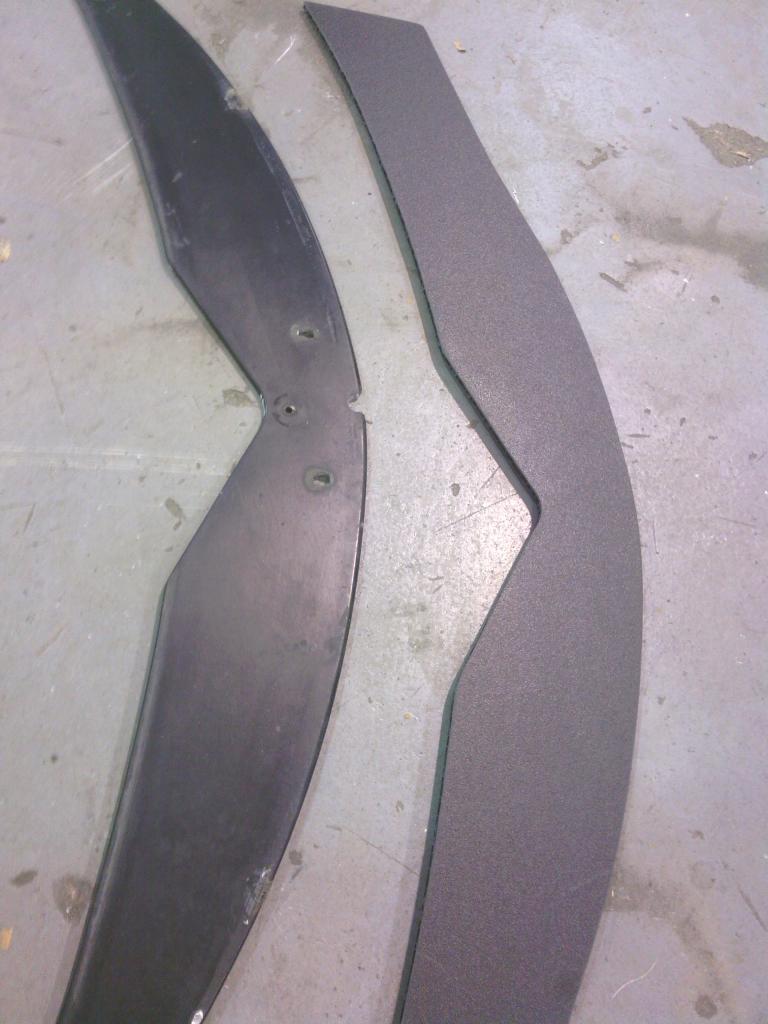 Time for a redesign. Fresh piece of board obtained plus some 20mmX20mm PVC angle and some nifty stainless flange head screws only 6mm long 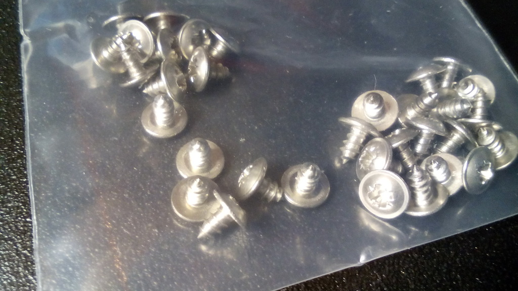 Ain't the Internet a wonderful place? Drilled the PVC to accept a 1/2" tube support 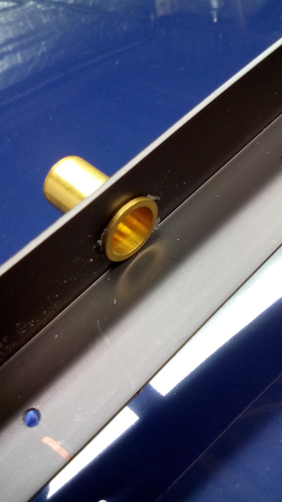 Screwed it all together 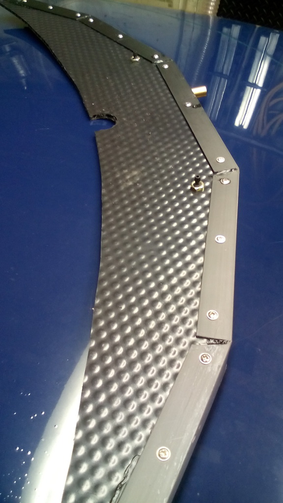 And upgraded to 2 washer jets 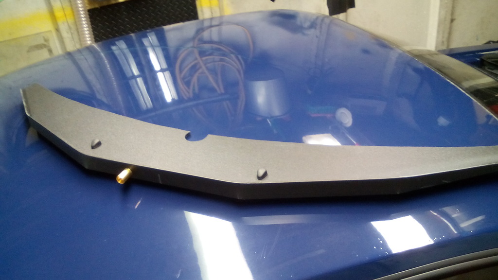 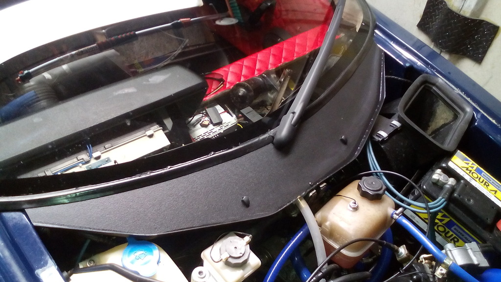 Piece of half inch PVC pipe on the brass tube support And 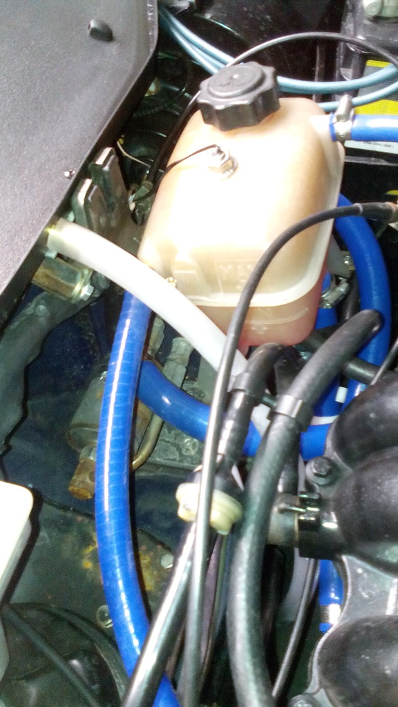 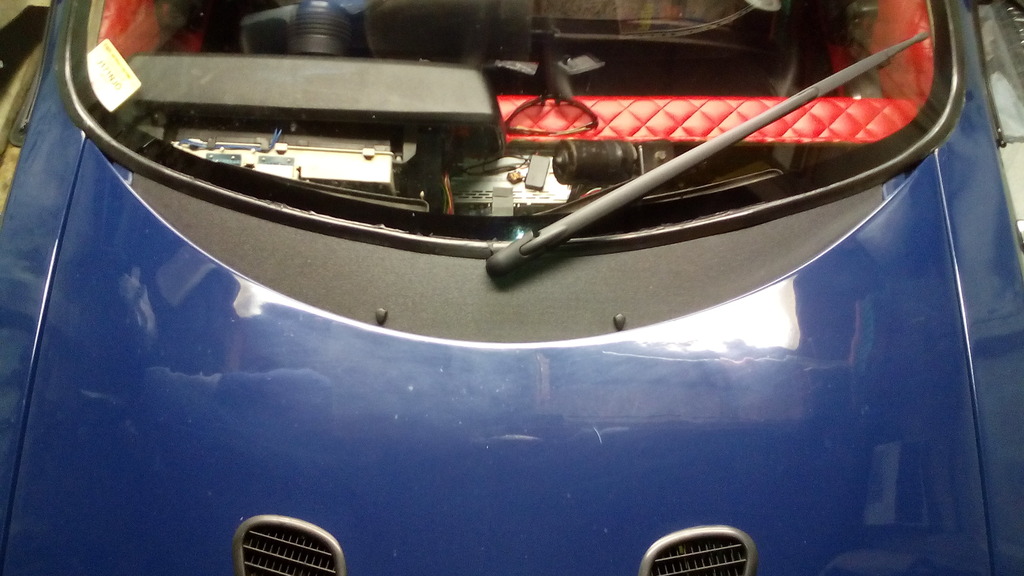 Works a treat, even copes with the hosepipe | ||
| Colinmac1330 |
| ||
| Member Posts: 93    | Awesome! by far the best one of these I have seen | ||
| Jin |
| ||
| Regular Posts: 159    | Cheers dude, much appreciated, hopefully I'll have a few more updates in a couple of days. | ||
| Jin |
| ||
| Regular Posts: 159    | Done a bit I left off last time having finished the lower dash and needing to sort the upper dash and screen ducting, first up was the screen ducting, originally the standard metro ducts bolted to the bulkhead had very little say on where the air blowed out of the dash top, but owing to the duct and demist vents being misaligned and an inch gap between the 2 they more just pressurised the inside of the dash structure than actually blow air at the screen, so a solution was sought. I had already routed 2 ducting hoses to the upper dash area, now I just needed a way to collect that air and focus it to where it was required, I decided to start from scratch, I had to make something that enabled the dash top to be removed on a semi regular basis (for one reason or another I’ve always got my head wedged in there) so I set to it, after producing a highly technical engineering drawing 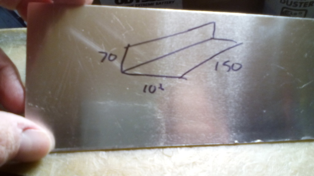 Got myself 2 bits of 3mm thick ally 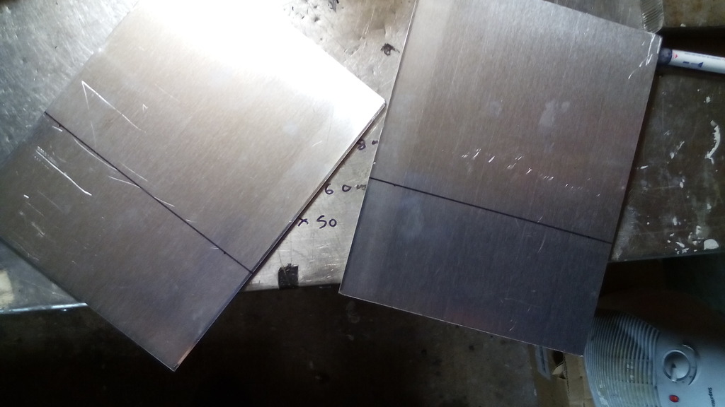 bent 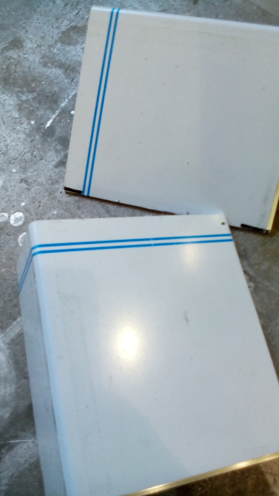 cut and 50mm tube welded on 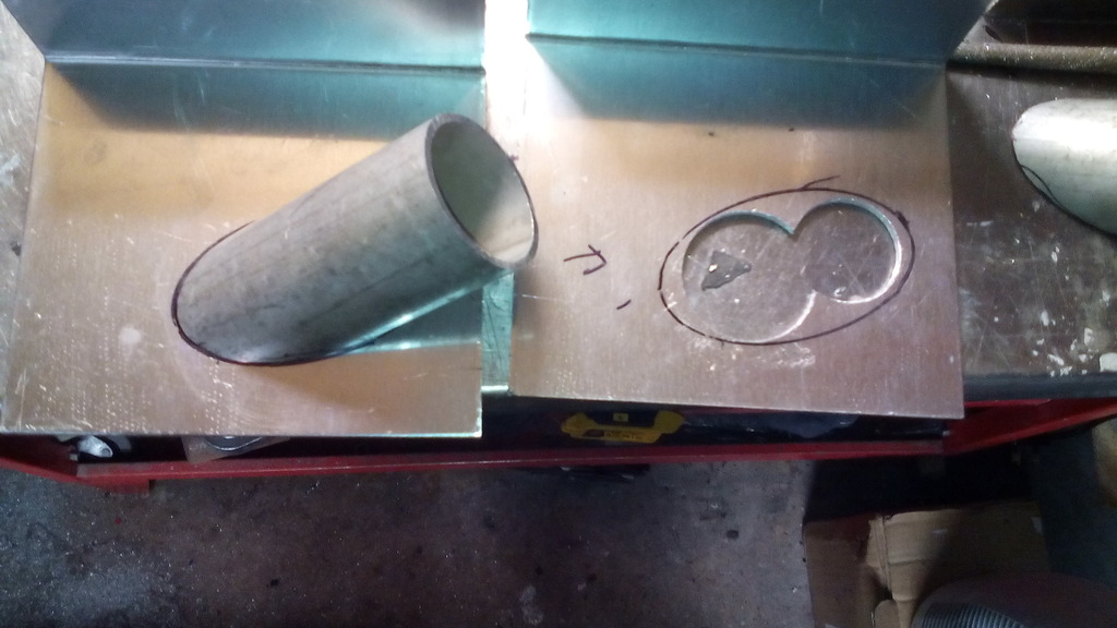 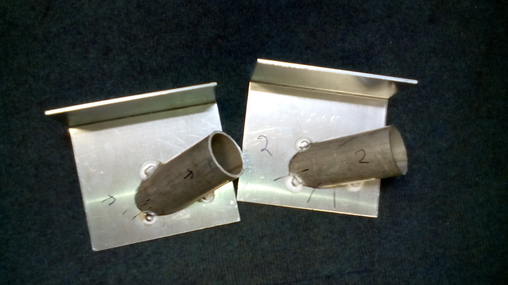 trued up on the bulkhead 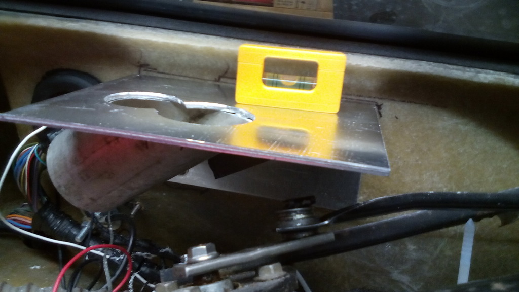 2 project boxes butchered up to form plenums 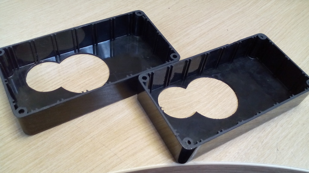 riveted and bonded into place 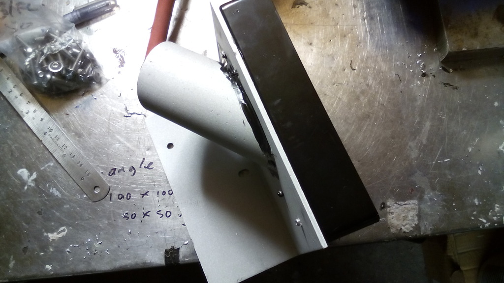 Connected up both sides, space was tight but do-able, both units are held with stainless bolts to the bulkhead so can be removed if required. 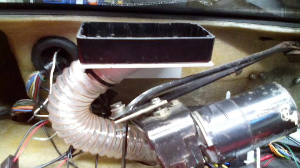 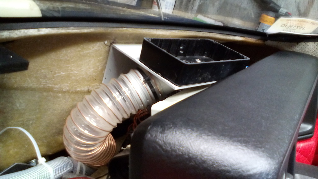 Onto the dash top itself, manky was the only word for it; it had to be changed, 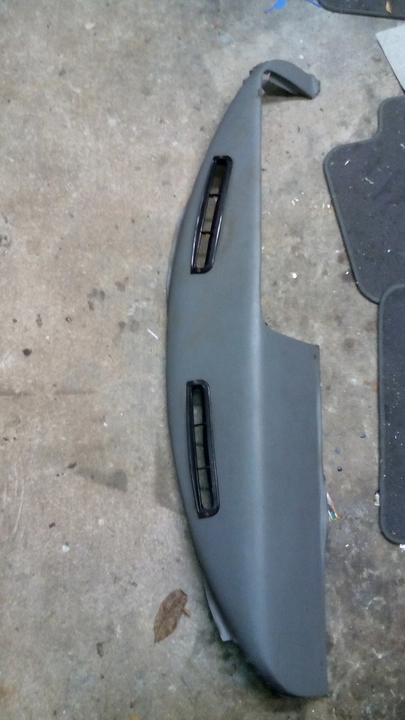 there was nothing classic looking about the classic mini demist vents either, and the vinyl was peeling all over and looked like it was bonded on with dried ox blood or something equally as weird... The gaps around the cowl and sides were so big you could read through them so this was to be addressed too, Once the vinyl was removed I identified the centreline of the dash 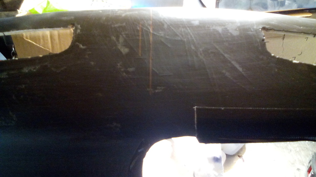 Which almost unsurprisingly was nowhere near equidistant between the 2 vent cut-outs already there. This too was to be addressed, is symmetry too much to ask for? I wanted the same small round directional vents on the dash top that I used on the lower cowl, so with a template in hand and the true centre line of the dash located it was just a case of taping the template in place and flipping it over to mirror side to side, simple but effective. 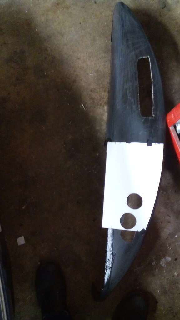 The old cut outs were plated over with some very thin ally sheet 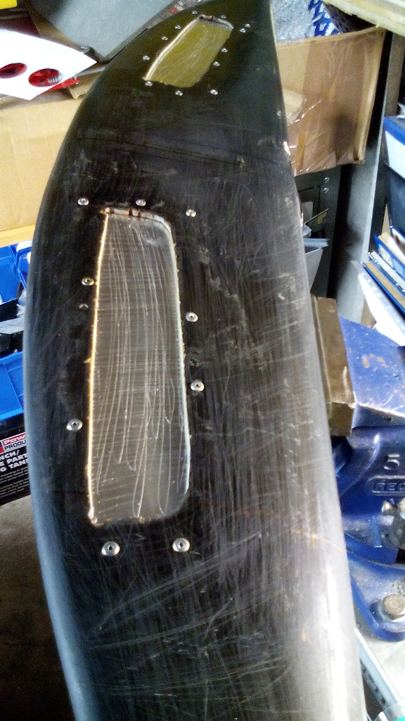 And filled in with lots of pudding, then sanded down with the new locations marked out after 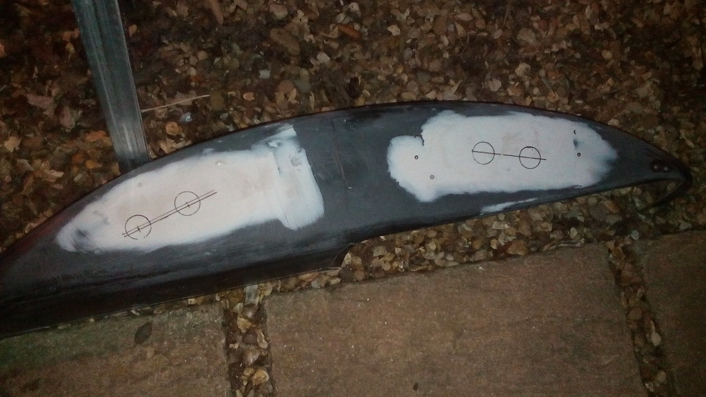 Cut and trial fitted 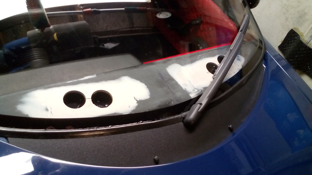 ….and you can see they they line up perfectly with the project box plenums I made underneath – almost like I know what I’m doing. 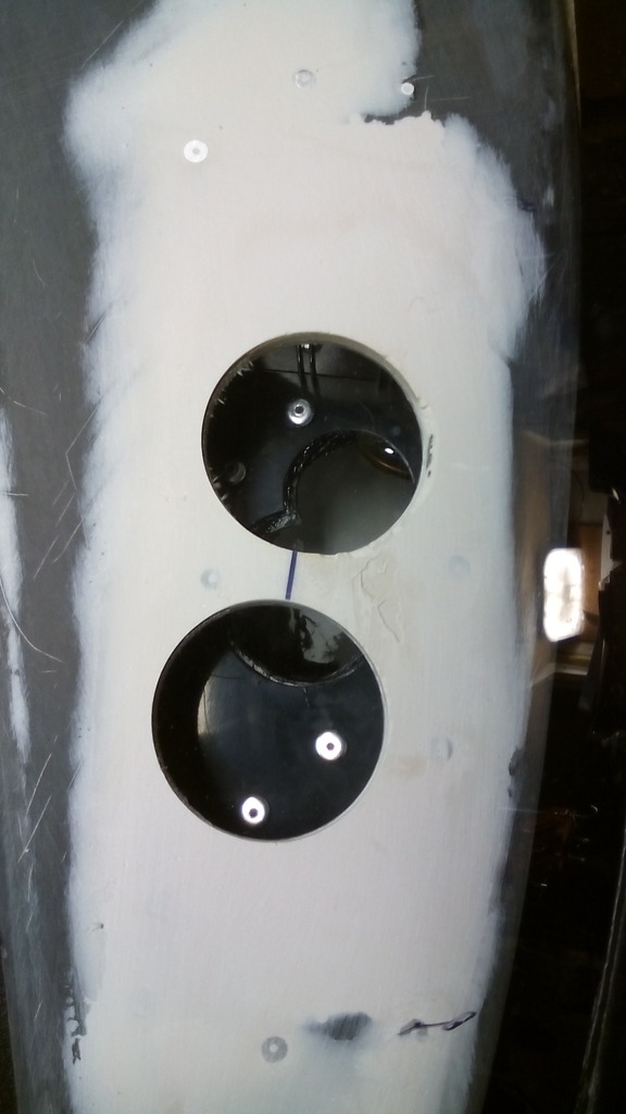 since I wanted no visible fixings I decided some time ago I would use high power magnets to hold the dash in place, easy to remove if needed, here is the upper centre one that latches onto a steel tab that was there originally from build to support the dash top – except now it holds the dash tight in place with no movement – handy because there is a 5mm gap between the dash top underside and the top edge of the project box plenums, so with some 12mm thick closed cell foam in place this makes the gasket for the demist vents and creates an air tight seal. 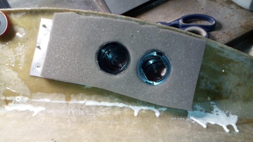 The driver side edge of the dash top had suffered a few knocks (not helped by my juggling antics) so a reinforcing strip was bonded and riveted into place here to keep shape. 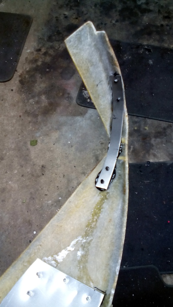 it was roughly now, with new vinyl in hand and a tin of evo stik in my grubby (and sticky) mits that I decided that a simple re-trim wouldn’t suffice, that the flat slab like facia in front of the passenger looked a bit – well flat and slab like, so I thought what could be done to break it up a bit and came to the only logical conclusion – fit a sat nav in it. this whimsical flight of fancy turned into a full on master plan and technical search when I found after a cursory peep on ebay that they were cheap as chips if buying a non-branded version and more features than I could ever imagine. The one I settled on was this one 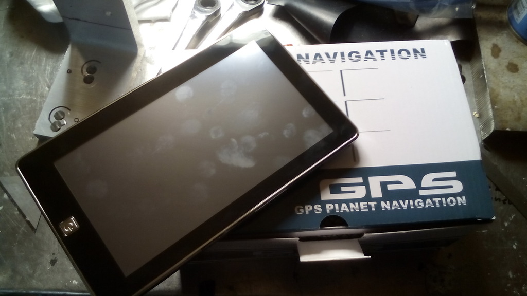 7” touch screen but more importantly the power / function button was on the front face bit like an iPad, most have it around the periphery which would pose issues if the device was mounted flush to or behind the dash surface. the plan was to cut out a shape in the dash top that would enable the unit to sit flush and use it as is, unfortunately upon opening the package it became apparent just what the grand sum of £30 got you, the outer most front screen wasn’t glass but a bit of plastic film stuck on – and not very straight either, the black surround edges weren’t flat and smooth (like an iPad) but all wobbly as if it was the result of an object nder 2s arts and crafts session (trust me I know), if you look at the photo at the reflection you can see the wavy nature of the outer surface.  feeling somewhat dismayed I considered my options, I didn’t see the point in spending hours and hours making the dash top perfect in every detail – accurate and symmetrical down to the last 1mm only to mess it up sticking a shoddy looking screen slap bang in the middle of it, so as you do when confronted with the concept of having to return an item in perfect unused condition for a refund, just like the "wet paint" sign where you need to poke it just to see I started to peel off the plastiky outer film - just to see, and much to my pleasant surprise what I found underneath was the main guts of a generic sat nav within the casing of another generic a sat nav (stick with me on this, its not as complicated as I'm making it sound) 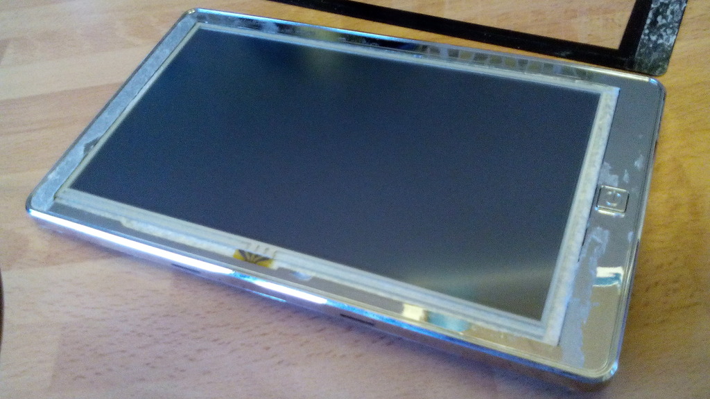 the screen revealed on this inner version was as you would expect – satin glass every bit as good as my Tom Tom, this does explain why the picture on the user manual looks nothing like that of the device in the box and putting that part number into google brings up several different designs in different cases but all exactly the same inside, what’s more is the operating hardware is media tek who are one of the biggest suppliers of chips for mobile devices inc Sony and Samsung along with TVs DVDs and pretty much anything, the navigation system is igo primo which is standard fit in some production cars and again mobile devices including branded sat navs, and in use it performs fantastically outperforming my tom tom by miles, the search function brings up details such as selecting a store by name as well as accommodation – campsites, garages, hospitals etc etc., it also works as a video player / reverse camera and even has windows installed operating as a PC, it has AV function for reverse camera (on order) and can search the internet with Google installed plus radio, radio transmitter, WiFi and loads more I’ve yet to discover – its truly remarkable. Back to the project, since id ripped off the outer cover I now settled on making a cut-out just big enough for the visible screen and mount this behind the dash top fascia. I trial fitted it to check it wouldn’t foul the wiper mech 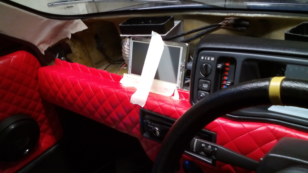 Then marked out the position 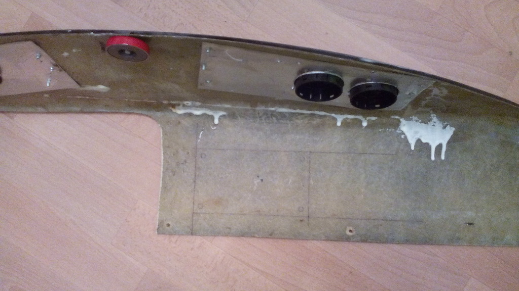 Choppy choppy 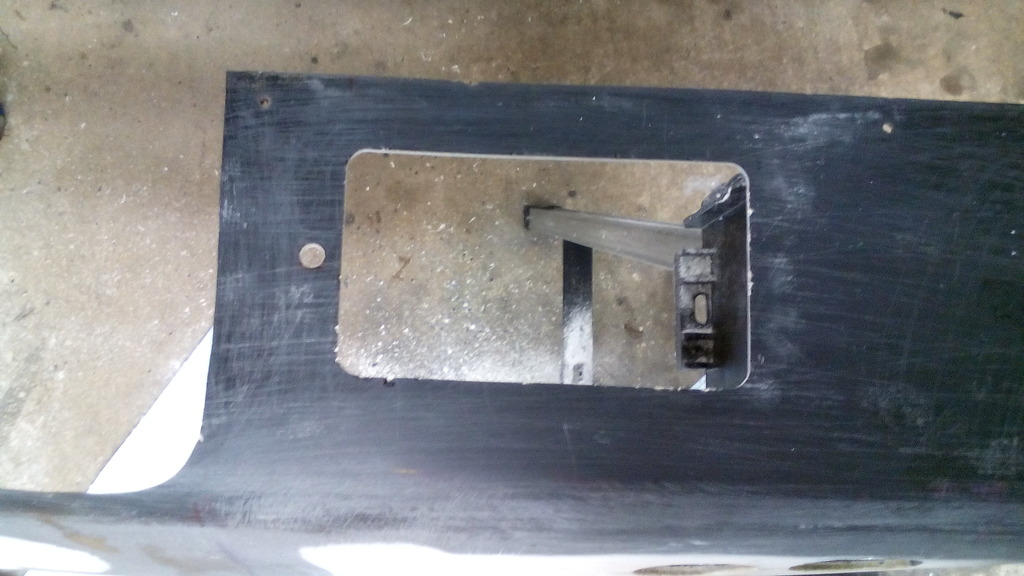 Gaffer taped it in a drove for a week like this to check functionality and reliability 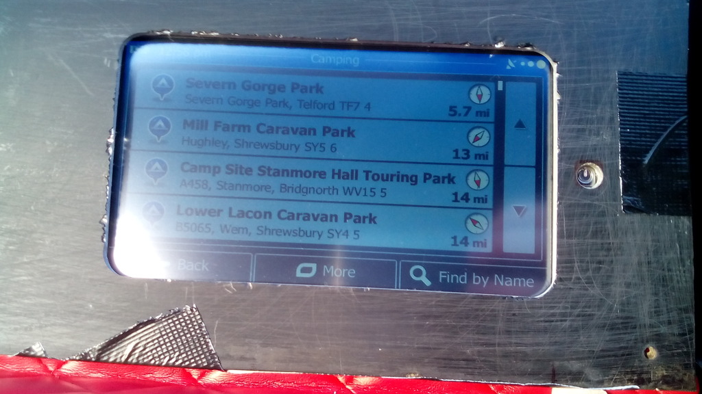 Once happy I set about making permanent bracketery 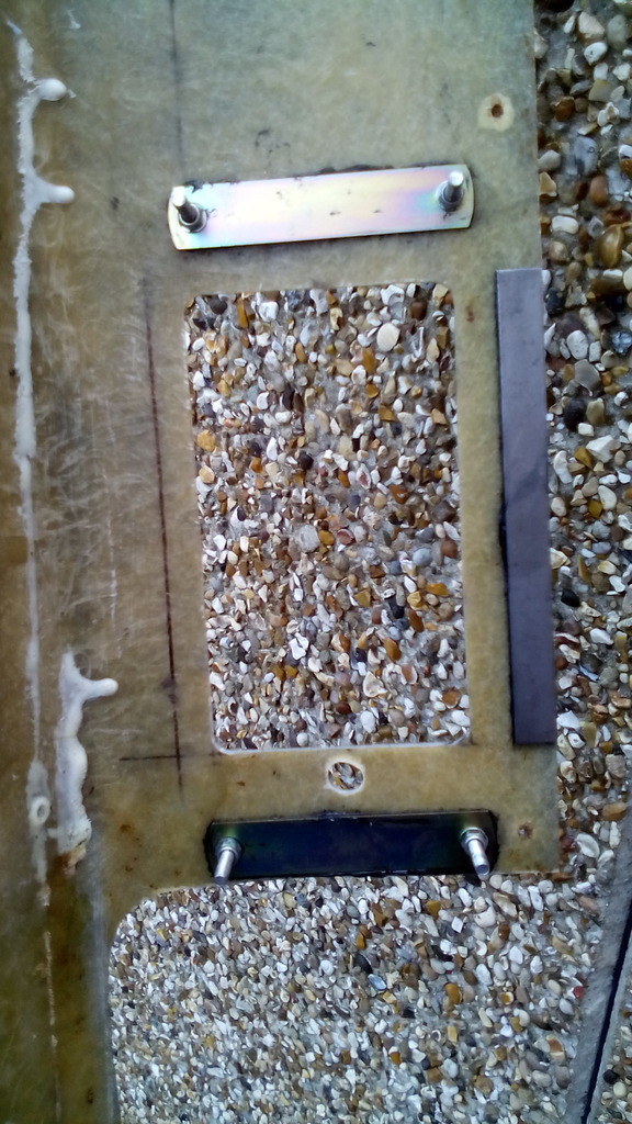 I had to reinforce the lower section of the dash top with a strip of sell to keep it flat, also whilst on the steel I made a right angle section to straighten out the left hand side since it had become slightly warped through age or something, this would also give me my second location point for a magnet to secure it with. 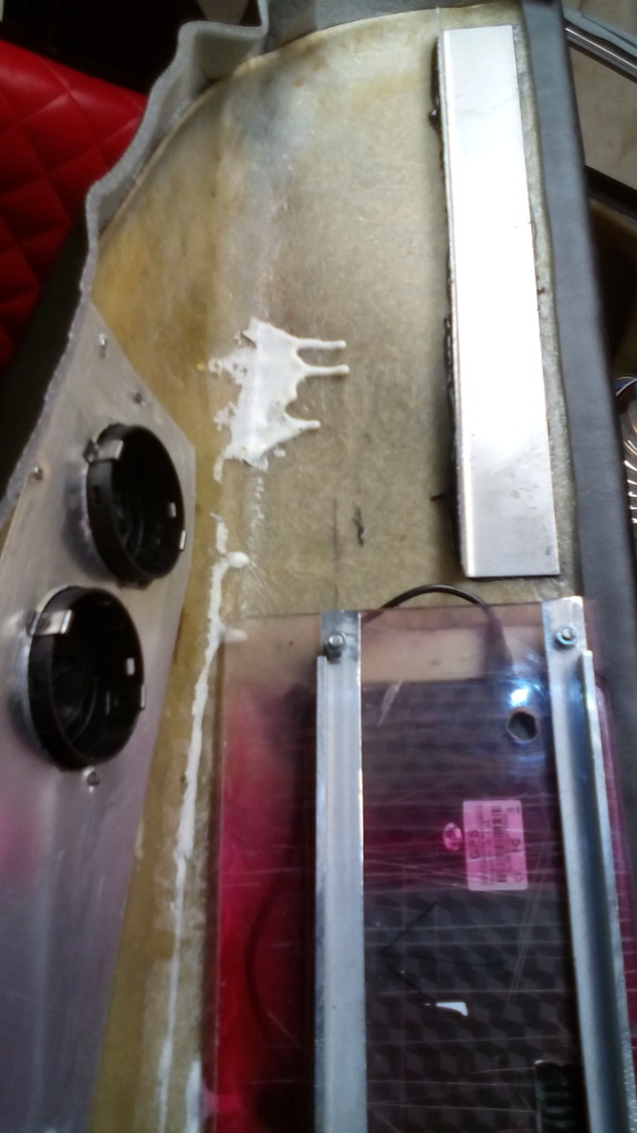 the whole dash was then covered in 4mm foam backed black vinyl – twice since I made a total monkeys breakfast of the first attempt. 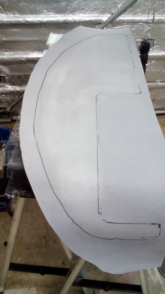 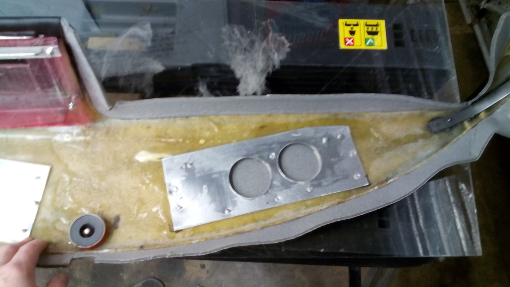 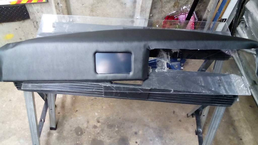 I purposely left an inch overhang all-round the edges, not to fold under and glue flat but to fold under loose and let curl back against the adjoining panels to seal all the big gaps mentioned previously – a bit like a lip seal, as It happens this was very effective since there are no gaps at all and the dash top looks like it was factory made to production car tolerances as a result. to enable operation of the main function button of the screen I made a cut out in the dash top for it then made an extension of the button by filing up a brass bush the same thickness as the fiberglass of the dash top thus enabling it to rest just behind the foam vinyl  One touch of the vinyl in that area allows full function of all the features as required but no unsightly buttons Quick trial fit of the screen, the rear bracket for the unit was made from an off cut of polycarbonate and 2 strips of ally angle to keep the shape  Second high power magnet on the lower dash in line with the steel angle strip on the upper dash, snaps tight and flush  I also purchased a module to hardwire the sat nav in place to become a permanent fixture  all done and working a treat, its set up so it springs into life as soon as you turn the key and switches straight to navigation mode, simply showing your location on a map as you drive which I quite like as you get to see upcoming bends – speed – traffic alerts etc. (I clearly watched far too much knight rider as a kid) and downloading videos into the memory card it keeps the little uns quiet at shows if they are a bit bored. 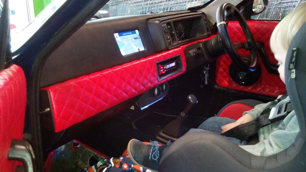 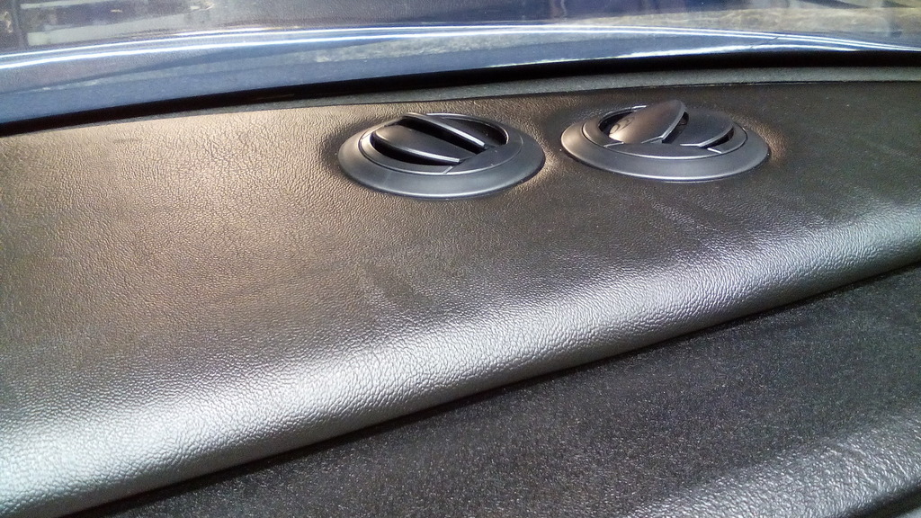 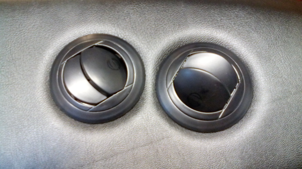 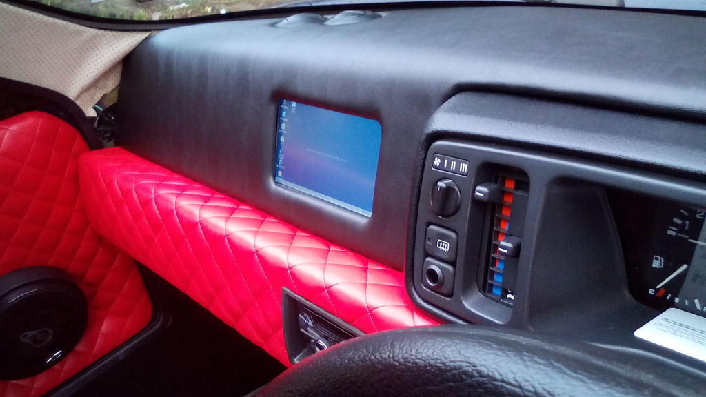 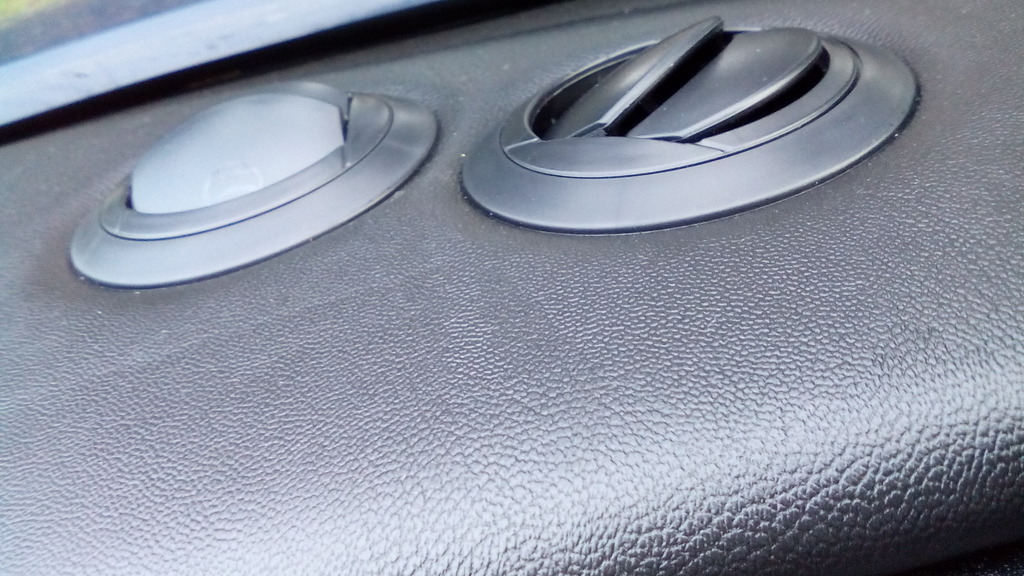 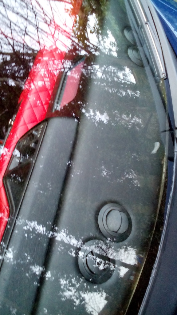 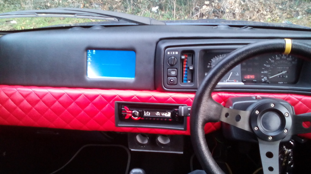 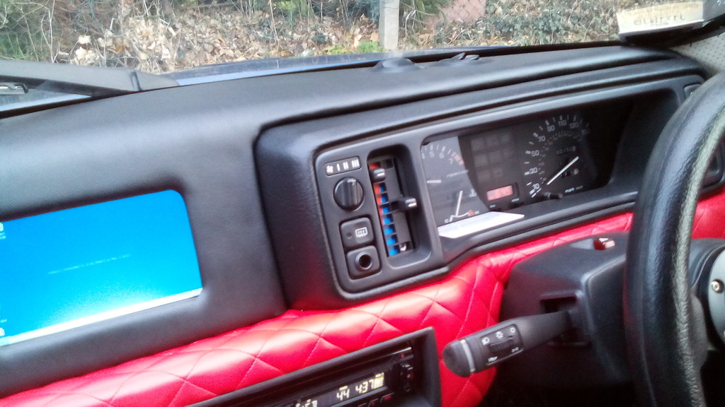 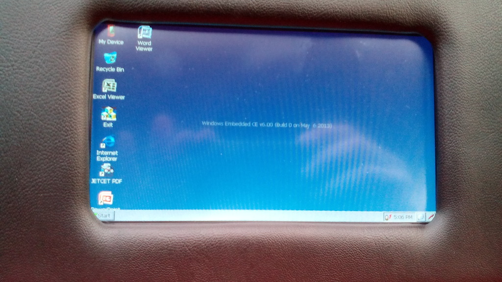  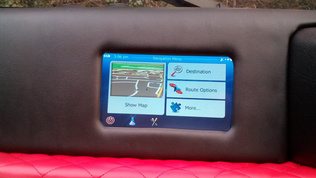 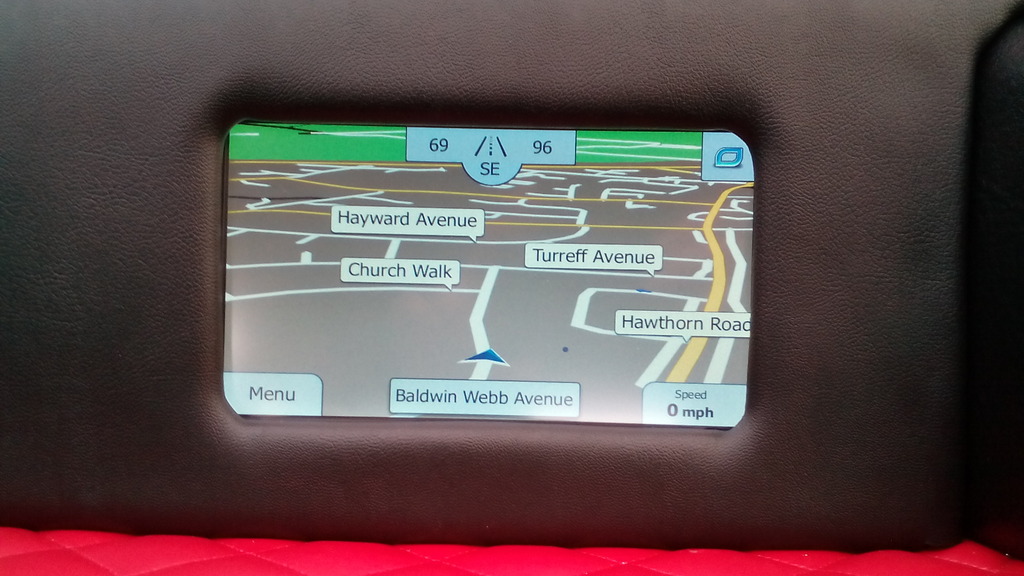 Excuse the lack of lower dash cowl in these photos but I’m currently wiring in a kill switch to this area. I also have, on a slow boat from china an SD card extender which is a ribbon with attached socket you use to extend the card reader slot so I can mount that (flush of course) into the dash facia somewhere along with a similar USB device splitter to enable a socket to be mounted on the dash to data transfer the sat nav via a laptop or phone but will also charge your phone when the ignition is on so not relying on a seperate charger, as soon as they arrive ill update you. Not bad for a car that didn’t even have interior lights fitted when I bought it. In other news I've had a brand spanking new alternator due to the old one shorting out and lunching the battery with it, all good now though 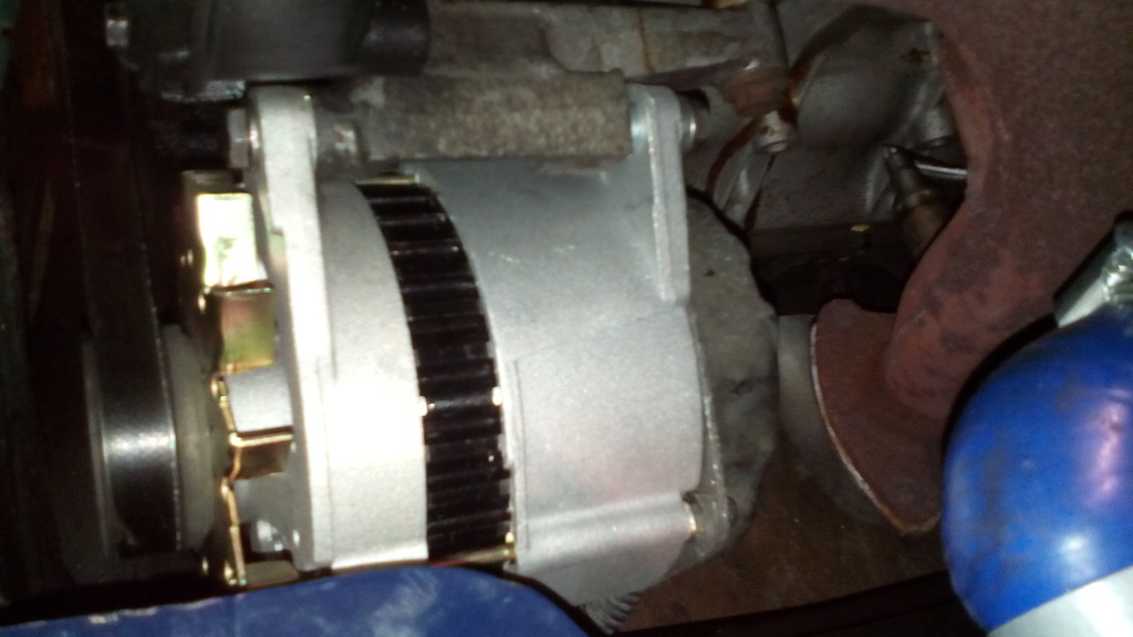 | ||
| Dave 20VTRO |
| ||
| Elite Veteran Posts: 925       Location: Thinking of vvc'ing my Roadster Brabus :-) | Sat Nav looks like it uses the 'iGO Primo' mapping, same as my truck sat nav, just advising that you may need to have access to the rear of the unit as the reset button is there, you use a ballpoint pen to press it, you will need to do this when the unit throws a wobbly, with the 2 units that I have, (same type, mapping ect), they are quite good, I have deleted the speed camera icons, they are too big, and Lane Assist, problem with that is, when you are exiting a motorway, Lane Assist puts the map into plan view, so you cant see the roundabout ahead to get into the correct lane until you are about 50yds away when the Lane Assist goes and the map drops back down into 3d mode. | ||
| Jin |
| ||
| Regular Posts: 159    | Done a bit more, well quite a bit more actually... the standard battery tray was a bit pants, it was positioned in such a way that the battery squashed the (unsupported) engine loom plug against the inner wing and the battery itself bared against the heater inlet duct, so ideally it needed to be moved in and forwards a touch, 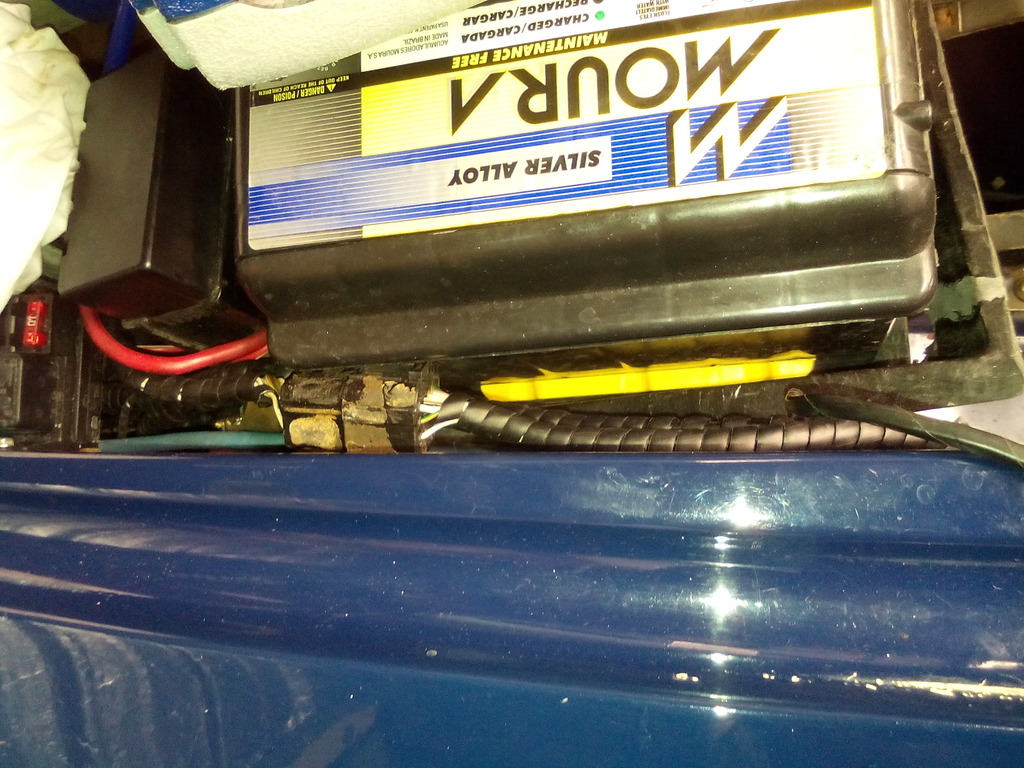 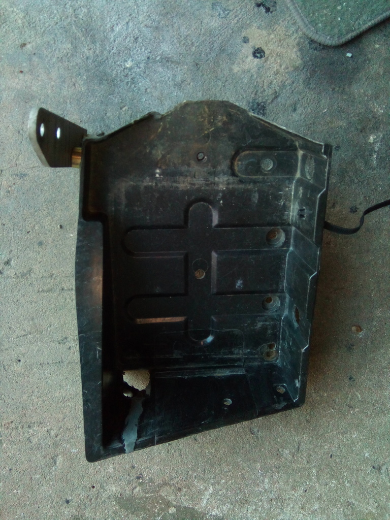 Additionally the engine bay fuse box was only supported on a crappy bracket that looked like it shouldn’t be there either so it would be nice to tidy it all up 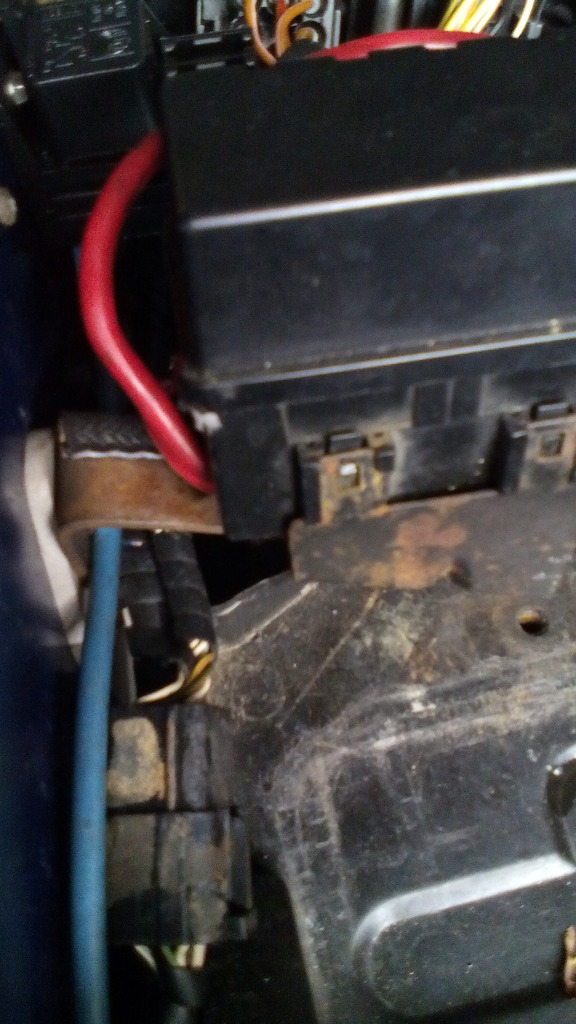 Lastly the battery tray was mounted at a downwards tilt – probably not a problem but I would like to have it sit level cos I'm a bit fussy like that. Not only that but it just didn’t look like it was mean to be there so I designed a new tray out of stainless, quite thin to save weight but with reinforcements in strategic places, and then made up some new brackets to support it out of aluminium, all trued up level on the car 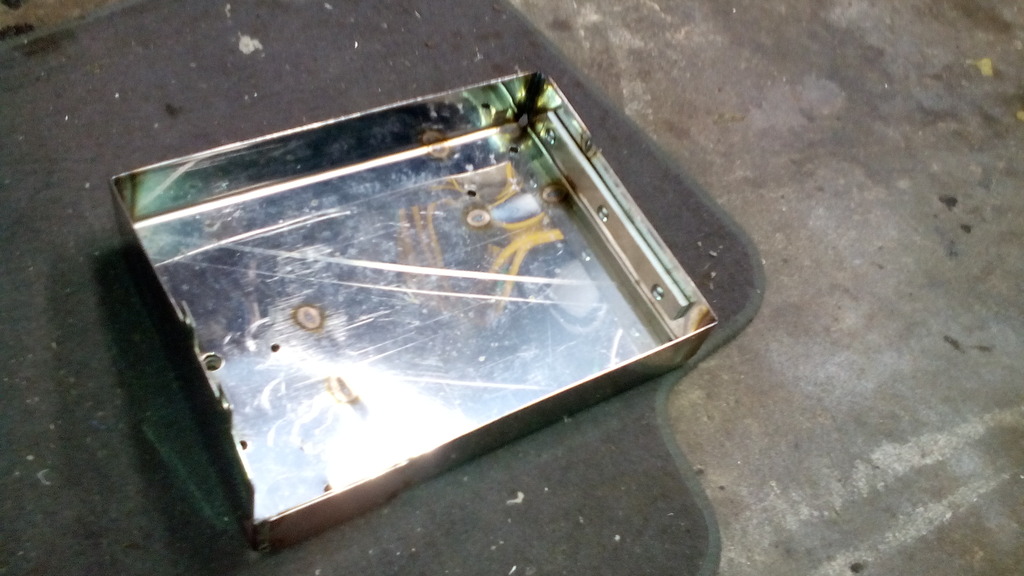  Painted  I then copied the profile of the locating tabs from the original bracket for the fuse box and copied it into the tray front edge  Much neater A bit of tweaking allowed me to raise the front of the tray and lower the rear, a quick check with a WD-40 straw taped to the front edge of the battery revealed a 10mm clearance with the bonnet closed.   The supporting brackets I made have M5 tapped holes to take P clips for the cables 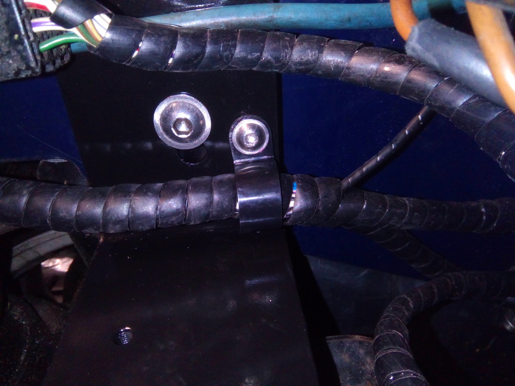 Much better All bolted on with stainless bolts I made a neoprene mat to go underneath 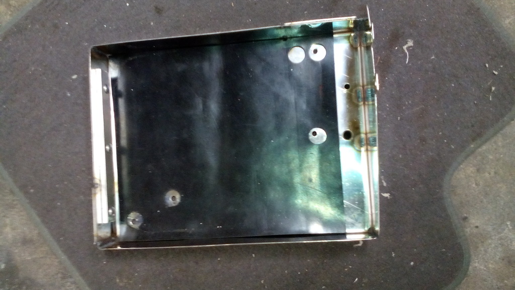 And since the stainless was relatively shiny despite being an off cut hanging around for a while it seemed rude to not give it a quick polish upup 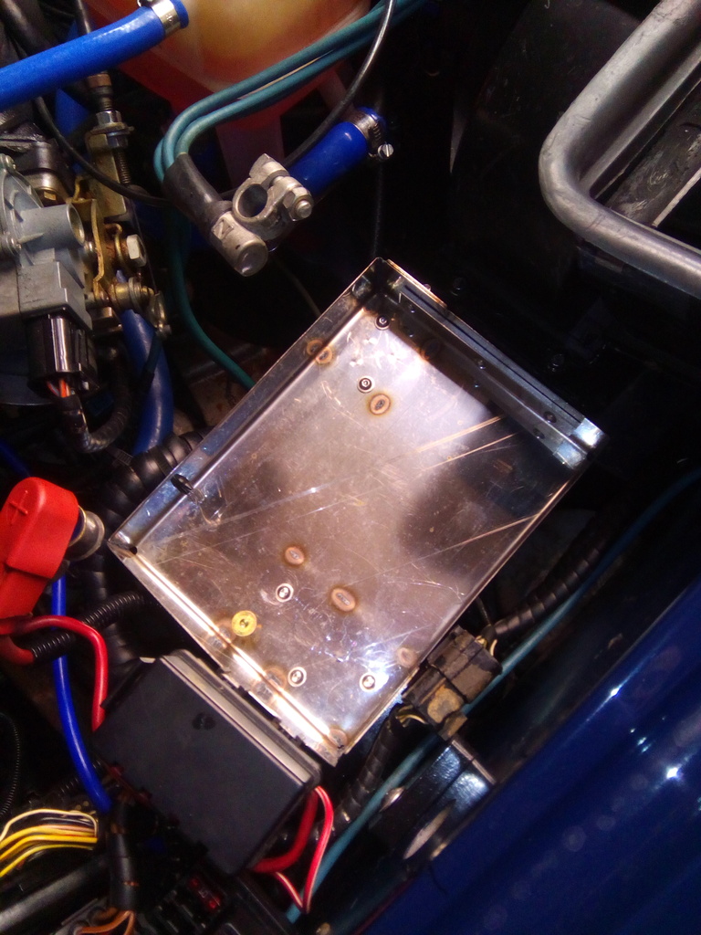 Finished and the result is something much more pleasing. 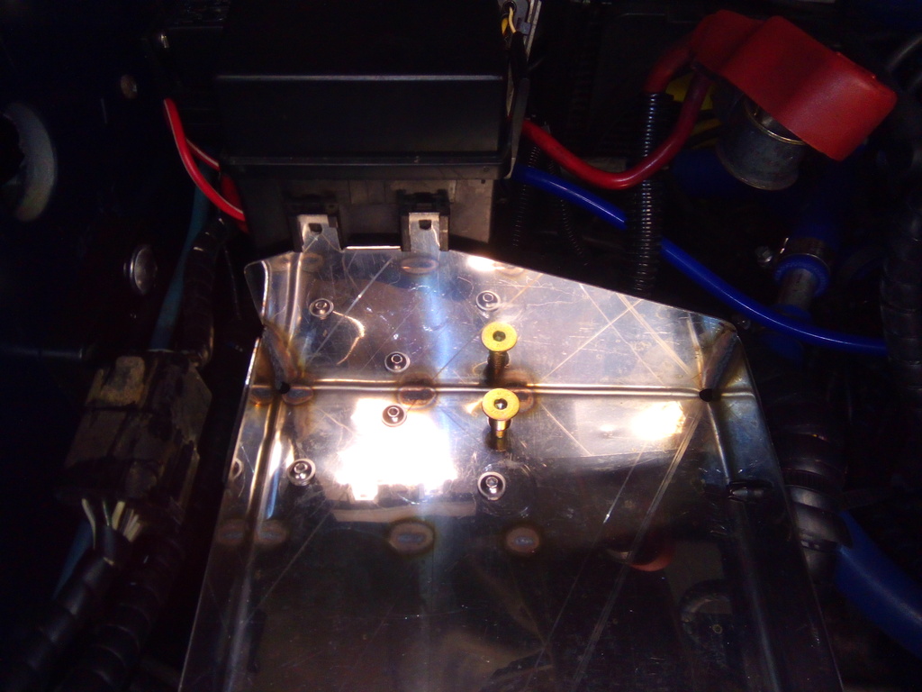 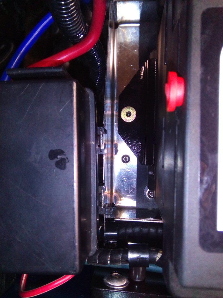 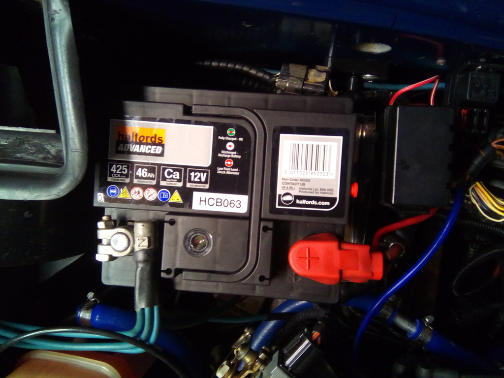 I now had the clearance I so desired at the rear edge to the heater inlet  Next up was new positive battery cable and kill switch, I had one in the quantum and I wanted one in here too, extra safety from all respects. I struggled to find a location on the dash I was happy with and / or room for, but eventually I decided to relocate the fag lighter to a more suitable front location and use the redundant hole to mount the kill switch thinking it would be better suited close to the driver anyway whereas the lighter socket was in the way a bit –win – winwin 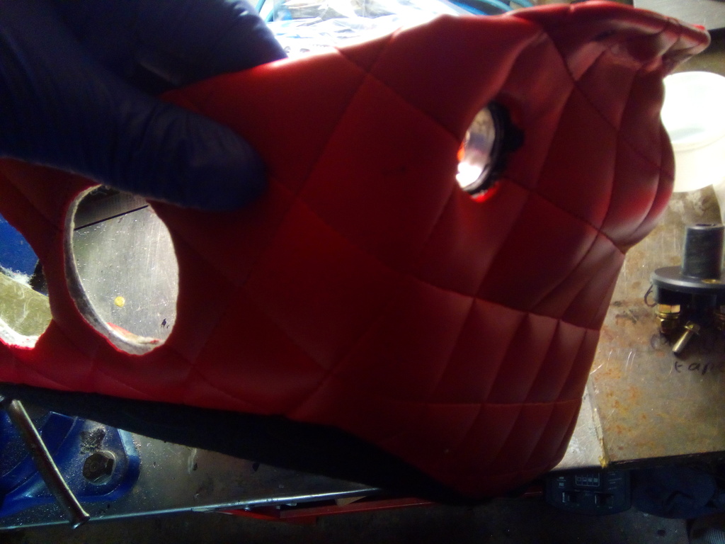 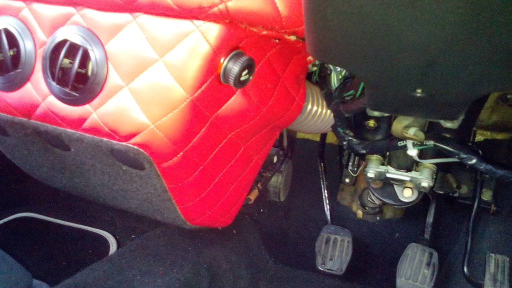 To secure it I made a 10mm thick ally plate drilled and tapped to suit, this was then bonded on to the reverse of the lower dash cowl to securely mount the kill switch. 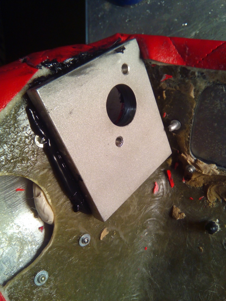 Once the switch was mounted I planned out the route for the cables, on the quantum I mounted 2 brass studs through the bulkhead and connected the to and return cables through these, but each connection is a possible failure point so I opted to keep as one continuous length if possible. I decided to cut a hole in the inner wing and the back of the bulkhead and pass the cables through there since there will be no metal in this area and the distance from battery clamp to inside is as short as possible to keep the risk of shorting in a crash or similar to a minimum. 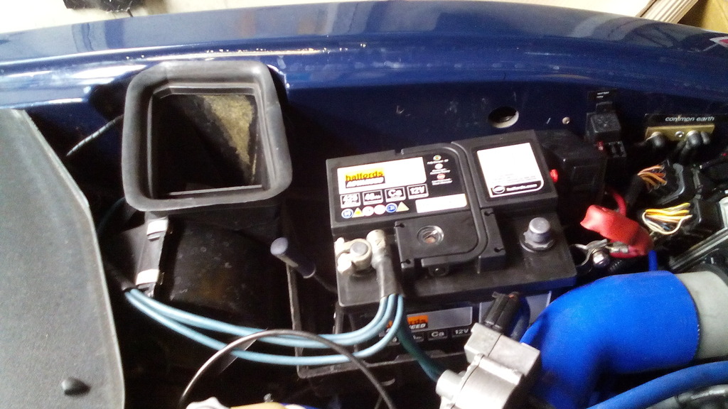 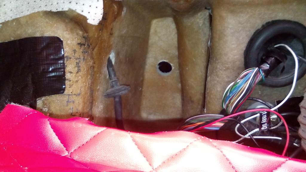 A second hole in the dashboard / bulkhead floor allowed the cables to pass through to the lower dash cowl where the switch is located. The cables were made up by myself as I did the negative cables; I’ve covered this before so just a couple of progress pics 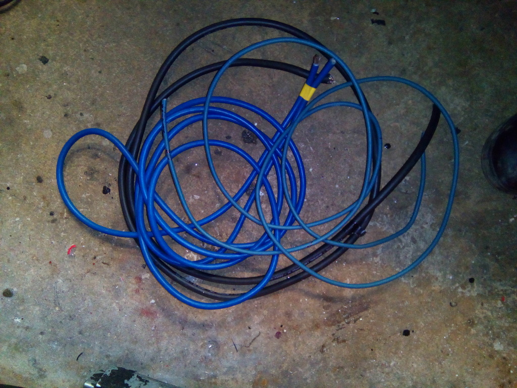 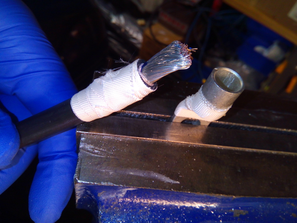 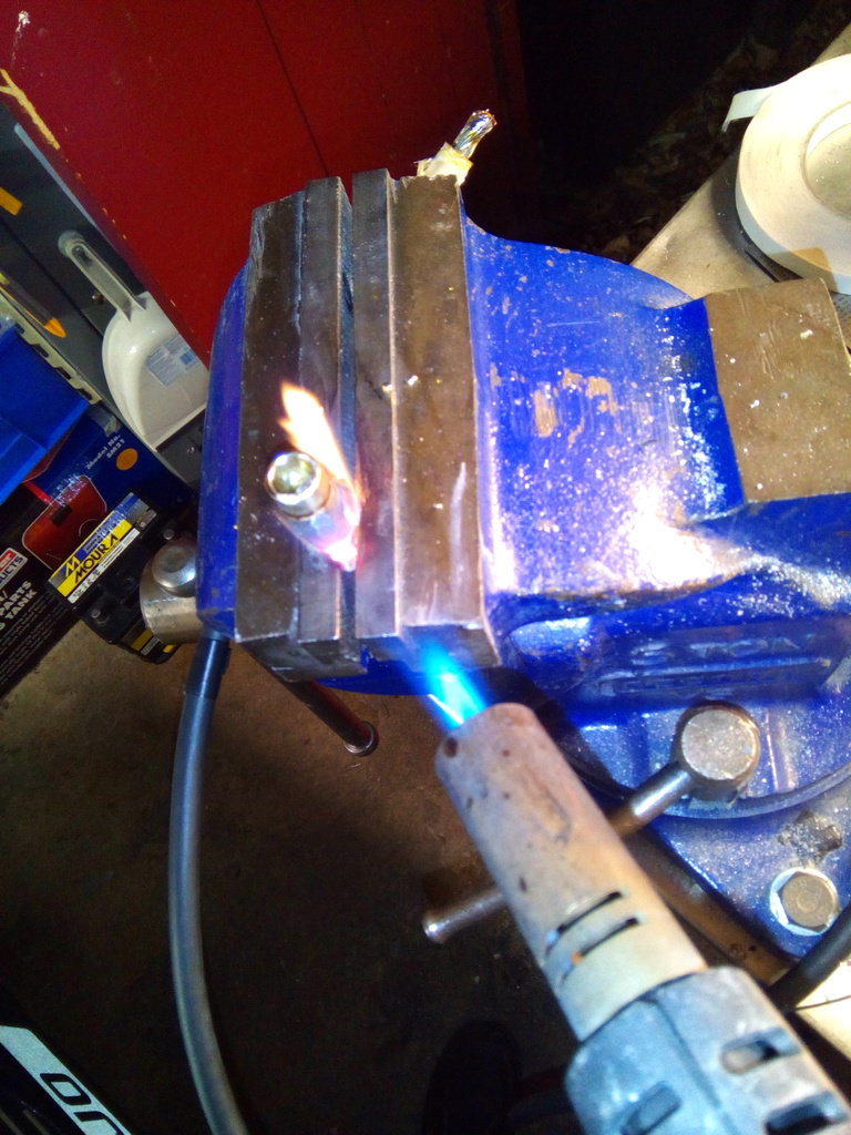 Once made up I had to make a grommet since I couldn’t find one big enough to take the cables off the shelf, this was made cutting an ally circle and some 3mm neoprene rubber sheet, this was held in by 3 M5 stainless studs bonded into tapped holes in the fiberglass    The cables all covered in adhesive lined red heatshrink and fed and routed through the car – this took forever and I hope I never have to change one in the future, but the result is much neater than anything that went before it, the cables have all been upgraded in size due to the additional length.  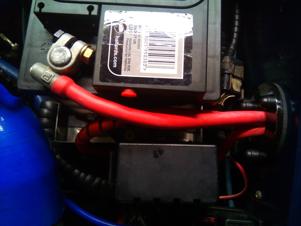 Its tight in the lower dash cowl but snug enough 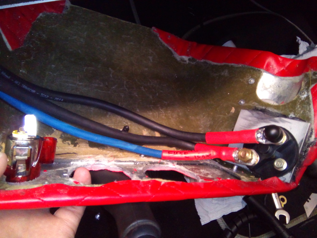 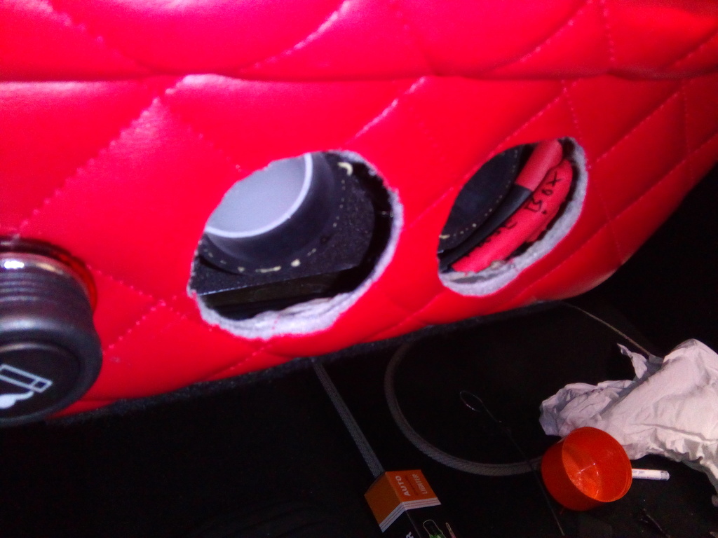 All finished and I’m happy with h result, the kill switch is not obtrusive but handy enough to get at in an emergency. Only gripe with using the old fag lighter hole was it’s a bit bigger than the kill switch 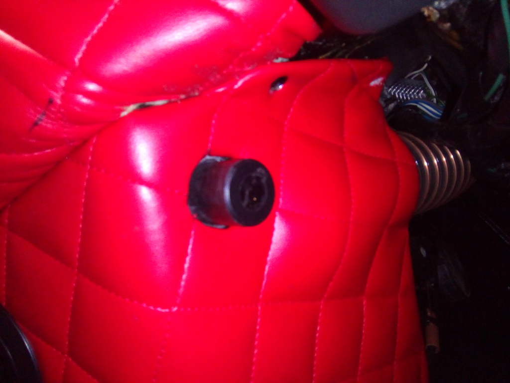 Rectified by chopping down a grommet I didn’t use 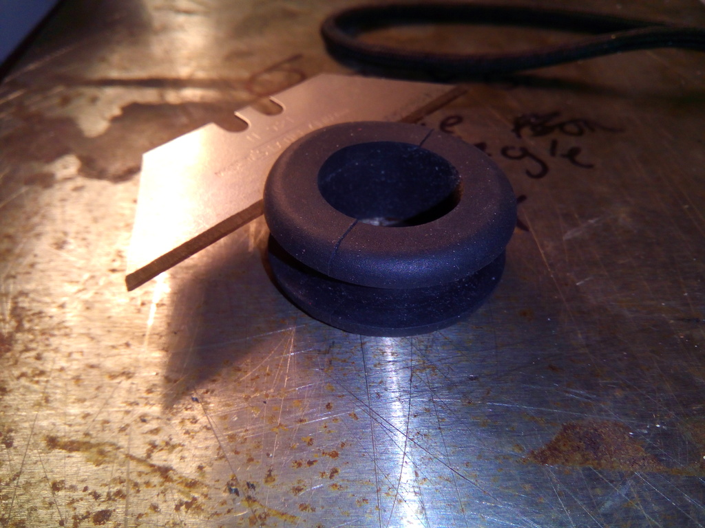 Tidy 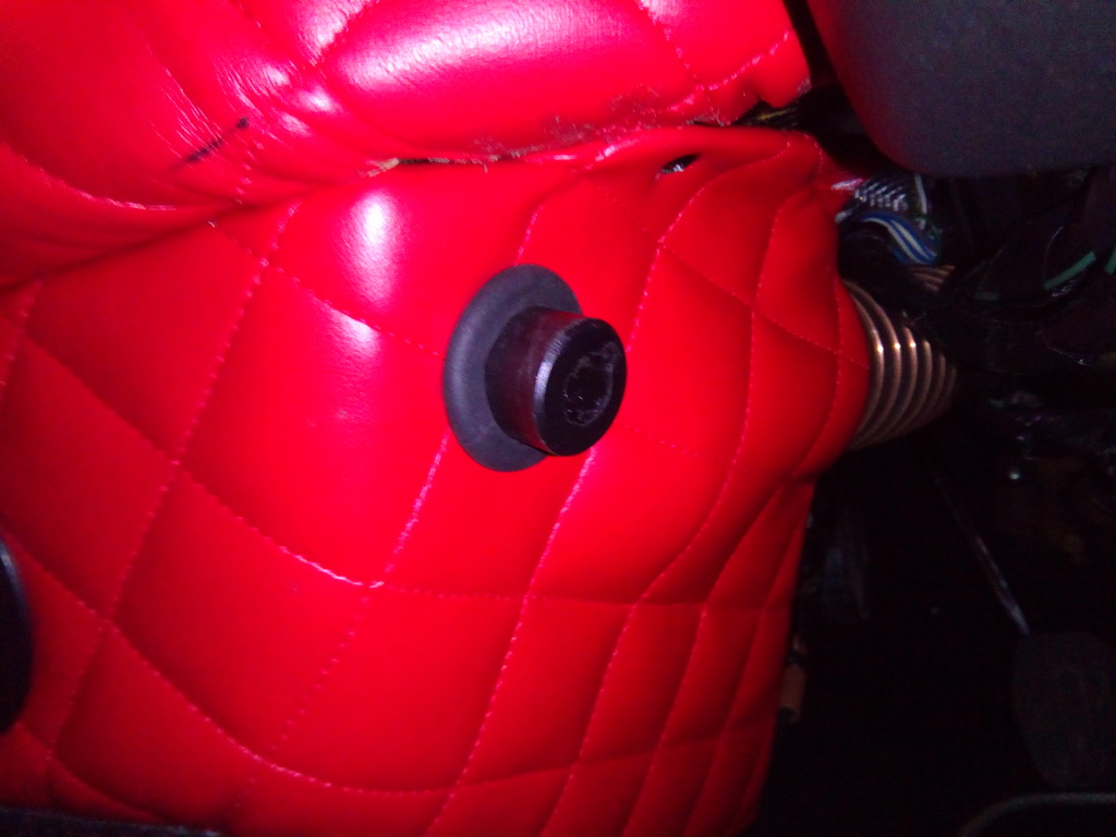 The fag lighter was re-located to the front and all works well Dash all finished now 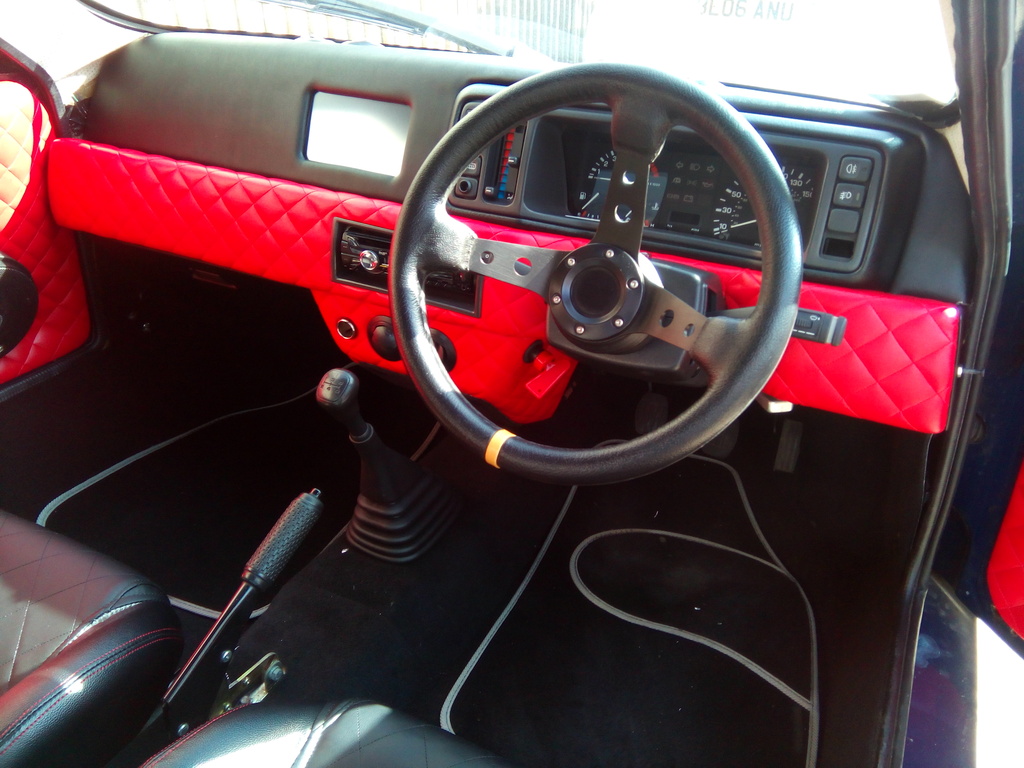 I’ve begun work on the SD card extender as that turned up last week; it appears to function well so just a case of slotting the holder into a switch blank. 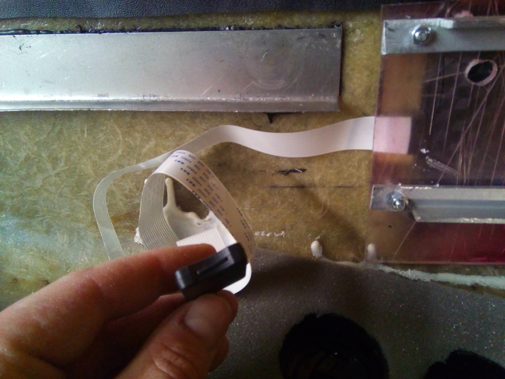 I’ll keep you posted on that bit | ||
| glyn-ellis |
| ||
| Elite Veteran Posts: 697      Location: leigh | Cool af.. it's always nice to see a well built kit car! It's so easy to throw them together because there isn't many parts that fit nicely so to see some one taking time to design and build the little bits is ace! I would imagine kits would be alot more popular if the company's built them like this | ||
| Jump to page : 1 2 Now viewing page 1 [25 messages per page] |
| Printer friendly version E-mail a link to this thread Jump to forum : |
| (Delete all cookies set by this site) | |
| Running MegaBBS ASP Forum Software v2.0 © 2003 PD9 Software | |