| Metropower Portal | ||
| ||
 Tony's Electrical bits (see CONTENTS in first thread) Tony's Electrical bits (see CONTENTS in first thread)Moderators: Jump to page : 1 Now viewing page 1 [25 messages per page] | |
| Technical Area-> Technical | Message format |
| gshaw |
| ||
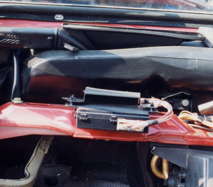
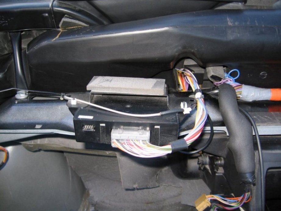
MP Admin Posts: 8747       Location: Greater London \ Essex | CONTENTS (so far) Alarm Central locking (inc. Maplin motor wiring) 3As to 5As conversion Electric Windows LED Indicators Photos/Schematics First Schematic gives details of C_locking Radio Windows - but see Windowssection for full detals Alarm - but see 3As to 5As conversion for full details 1.0 ALARM SENSITIVITY I found that to lock/unlock (arm/disarm) my Ascot R100 etc you have to stand very (very) near to the car to use the transponder (fob). Even then a second blip may have been required. 1.1 5AS ALARM On investigation it was found that on the 5AS alarm, the aerial was buried in the wiring harness to the alarm. The length was only approx 110mm. Colour White/Yellow. This is very bad RF practise. You don’t bury an aerial in effectively a copper shroud. So I removed this wire and replaced it with one 346mm long. This is half wave length for the nominal transmit frequency of 433MHz. I dressed the wire behind the heater and cassette box held in place by tie wraps and to stop snagging etc etc. The length does not have to be that accurate – say +/-10mm. With this little modification, I can now lock/unlock (arm/disarm) the car with a range of about 20ft and can be done through my lounge window. 1.2 3AS ALARM With respect to the 3AS alarm – this has a coaxial connection using coaxial cable. Importantly this cable is not buried in the harness. The length of this cable is just over 346mm so need not be modified. Again for slightly better response it can be dressed, like the 5AS Ae behind the heater and cassette box. 1.3 SELF DIAGNOSTICS -- 5AS ALARM -- FROM THE ROVER RAVE MANUALS The anti-theft alarm ECU contains a self diagnostic feature which tests and confirms inputs to the ECU. When in this mode, normal functionality of the ECU is suspended. The following procedure must be followed to enter self diagnostic mode. The procedure must be completed within 5 seconds. • With driver’s door closed, press the sill button down • Move the ignition switch to the on, then off and then on position • Lift the driver’s door sill button. Successful entry to the self diagnostic mode is confirmed by a brief operation of the vehicle horn. The engine will become immobilised and the MFU will emit a two tone sound to confirm that the engine is immobilised. Failure to enter the self diagnostic mode indicates that the ECU is not receiving sill up or down or ignition switch input. A spare vehicle key will be required to test the key barrel switches. The following inputs can be tested and confirmation of receipt of the input is confirmed by a brief flash of the LED in the instrument pack... Sill button Press the driver’s door sill button down, the ECU will immediately move the sill button up to unlock the doors. Driver’s door open Open the driver’s door to activate the switch on the ’A’ post. Passenger and rear doors Open the passenger and rear doors to activate the switch on the ’A’ post and the ’B/C’ posts. Bonnet open Open the bonnet to activate the bonnet open switch on the bulkhead. Tail door open switch Open the tail door to activate the boot open switch in the tail door latch. Key barrel switches Operate the driver’s door key barrel switch using the spare key. Self diagnostic mode is exited by moving the ignition switch to the off position. 1.4 PICS Apart from pic. of 5AS alarm, I have also included trace of transponder response taken on a Spectrum Analyser at work. This was my fob. This is basically amplitude shift keying i.e. power on power off to produce the code. (Well --- someone maybe “vaguely interested” in this one!!) 2.0 CENTRAL LOCKING CHECKS The standard Rover door actuators (made by Rockwell) are known to be problematic and are expensive to replace. Maplins do a much cheaper version. WIRING FOR ROVER CONNECTOR TO MAPLIN MOTORS When replacing Rover motors for Maplin ones you'll need to solder the original c\l connector onto the Maplin item, wiring is as follows... DRIVER Pink/purple ---- white Purple-----------green Orange----------- blue Orange/purple----brown Black------------black PASS Pink--------green Orange------blue The main problem is with the driver’s door actuator. This has two sensing wires back to the alarm. If the sensing is not working and the alarm does not have that earth signal from the door actuator it can put the alarm into undocumented (funny) modes and hence difficult to arm/disarm the alarm. The LED also does not flash correctly. I had one system where the central locking started pulsing – off - on - off - on etc. Firstly disconnect the driver’s central locking door harness by the right side of the fuse box. (Quite awkward to get at.) Referring to my drawing, the five wires in that connector are:- Orange ---> pos/neg power to actuator from alarm Pink ---> pos/neg power to actuator from alarm Orange/Purple ---> sensing back to the alarm Pink/Purple ---> sensing back to the alarm Black ---> earth used by the sensing On the female connector (car side); with a DMM, check that the black earth wire does go to earth. If a poor earth then check connection under bonnet at earth bonding point by washer bottle. The earth wire is taken to this point. If that is OK then :- Connect an earth wire to the Pink/Purple lead. If the earth is good in that harness then a simple 5cm jumper lead can be used to that black earth wire. Sit in the car and close the door. Now activate the alarm using the fob. The passenger door and boot actuators should work and the alarm should correctly function arm/disarm etc and the LED should flash correctly. If all this is ok then it means that the driver’s door actuator has gone u/s. If there are still problems with the central locking then disconnect, in turn, the passenger door actuator and the boot actuator and try again with all doors closed. At least now the alarm should correctly function. If the driver’s door actuator is faulty, until you get a new one, leave that shorting wire in place. It will do no harm. On cars with no central locking where that Pink/Purple wire goes into the alarm a black earth wire is permanently fitted in lieu. Again see my drawing. 3.0 3AS TO 5AS ALARM CONVERSION This schematic details the conversion from 3AS to 5AS alarm. The internal picture of the alarm shows how to wire the relay into the alarm for the horn circuit. PHOTOS - SCHEMATICS Click the link below the thumbnail to see a h-res image. 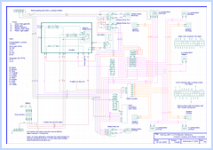 Click for hi-res version 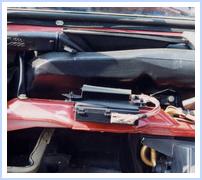 Click for hi-res version 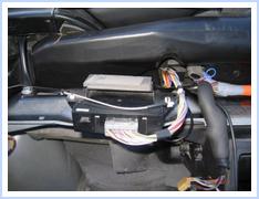 Click for hi-res version Click for hi-res version 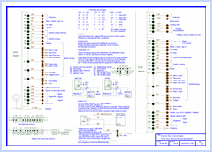 Click for hi-res version 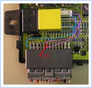 Click for hi-res version | ||
| tonyb |
| ||
 Electrical genius Posts: 1310 Location: East Devon | THIS SCHEMATIC DETAILS THE WIRING CONNECTIONS FOR ELECTRIC WINDOWS  (WindowElec_CD_01.gif) Attachments ----------------  WindowElec_CD_01.gif (97KB - 361 downloads) WindowElec_CD_01.gif (97KB - 361 downloads) | ||
| tonyb |
| ||
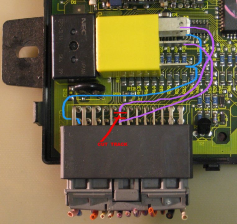
Electrical genius Posts: 1310 Location: East Devon | LED FLASHING INDICATORS If LED bulbs are fitted then the current drawn by them is much lower than conventional bulbs. If the all bulbs are changed ie front, back and side the current is reduced from approx 4Amps to about 200mAmps, so the flasher unit now thinks there is a blown bulb and the flash rate is doubled. This problem is very easy to overcome. In the flasher unit there is an IC that monitors the current via a shunt resistor in series with the relay. There is a finite voltage drop across that resistor that is compared with a reference voltage in the IC. If that voltage drop is too low, due to lower current being drawn due to a blown bulb then the flash rate is doubled. It looks like there are two variations to this flasher relay unit. Pics shown. One has a link from the 12V power to the relay and the other has a strap direct to the relay. Because the value of that resistor is very very low ( 30mOhms) it is actually the wire link in one and the strap in the other type. So how to overcome the problem. A good voltage drop is wanted so why not 0V / ground. To achieve this just cut the track between pin 7 of the IC and relay and leave it floating. This works. But it is not very good practise to leave IC pins unterminated / floating so I have tied mine to the 0V ground with a 4k7Ohm resistor. Any value will do between 1kOhm and 10kOhm. As can be seen I got mine direct from Farnell but Maplins would do a similar. Without checking I think it is +/- 1% and ½ watt. But tolerance is not that important or power rating. You may be able to get one from your local radio/TV shop. PS I have not fitted LED bulbs but just thought I would have a look at the problem. PS PS Please do not add comments to this thread as this sticky is getting rather messy now. tony 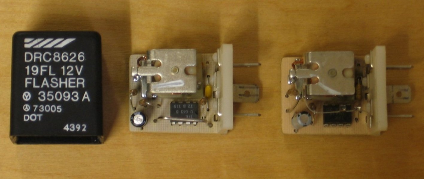 (RelayFlash_01_50.JPG) 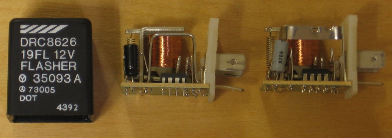 (RelayFlash_02_50.JPG) 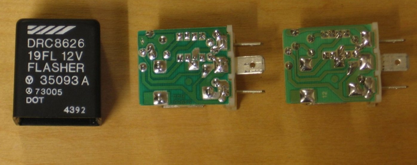 (RelayFlash_03_50.JPG) 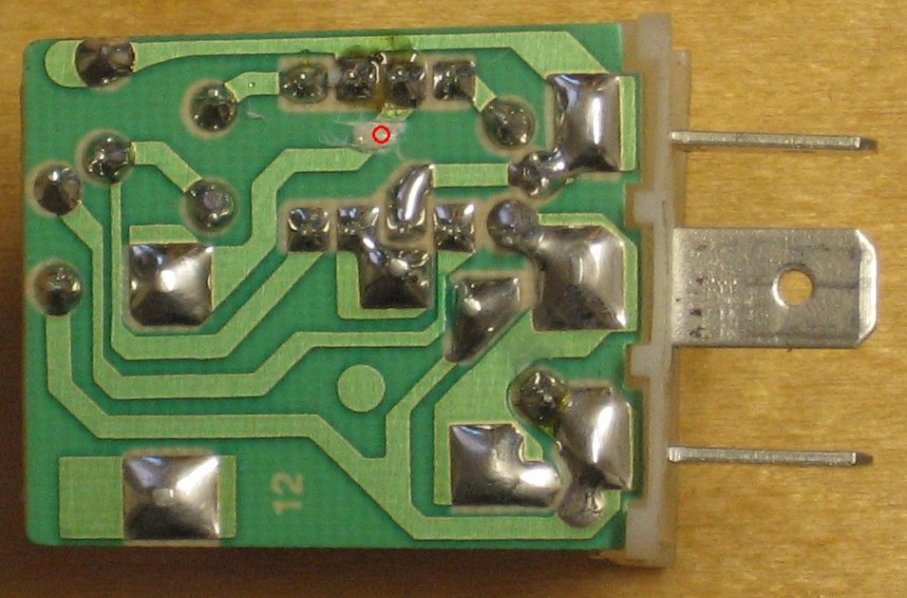 (RelayF_cut.JPG) 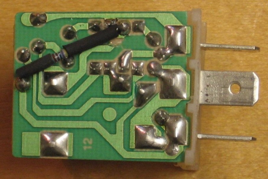 (RelayF_resistor.JPG) 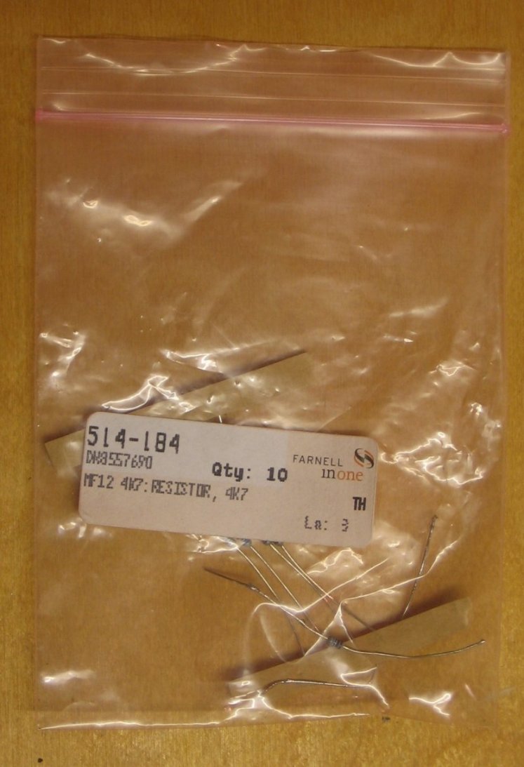 (RelayF_Farnell.JPG) Attachments ---------------- RelayFlash_01_50.JPG (90KB - 340 downloads) RelayFlash_02_50.JPG (96KB - 332 downloads) RelayFlash_03_50.JPG (96KB - 324 downloads) RelayF_cut.JPG (98KB - 331 downloads) RelayF_resistor.JPG (90KB - 341 downloads) RelayF_Farnell.JPG (98KB - 338 downloads) | ||
| Jump to page : 1 Now viewing page 1 [25 messages per page] |
| Printer friendly version E-mail a link to this thread Jump to forum : |
| (Delete all cookies set by this site) | |
| Running MegaBBS ASP Forum Software v2.0 © 2003 PD9 Software | |
